|
 Feb 3, 2010 - Horizontal Tail (HT) frames require measuring and attaching bottom L brackets to obtain proper length.
Also, as seen later, having the bottom L angles detachable makes installation easier.
|
 Feb 3, 2010 - 30x70 mm nylon fairlead is attached to top of the forward HT frame. Fairlead trimmed and ready for riveting
to frame. This fairlead will be used as guide for elevator control cable.
|
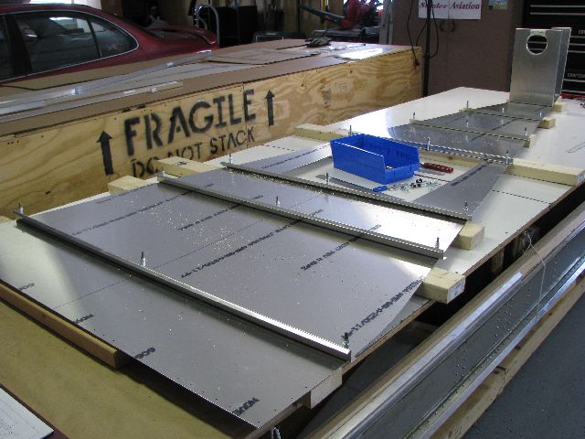
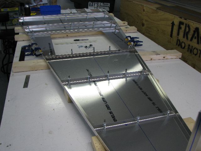
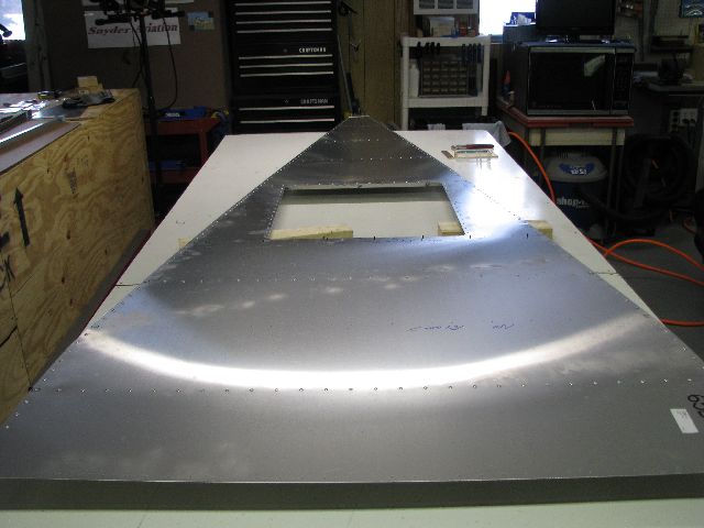
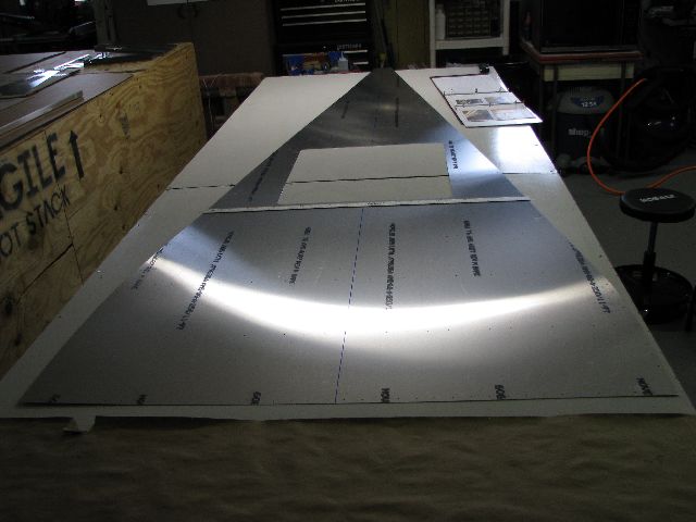 Feb 3, 2010 - Laid out rear fuselage bottom skin, marked center line, and deburred edges. This side will be inside the
aircraft, looking back to tail. The square cutout in the center will provide access through a drop-down door.
|
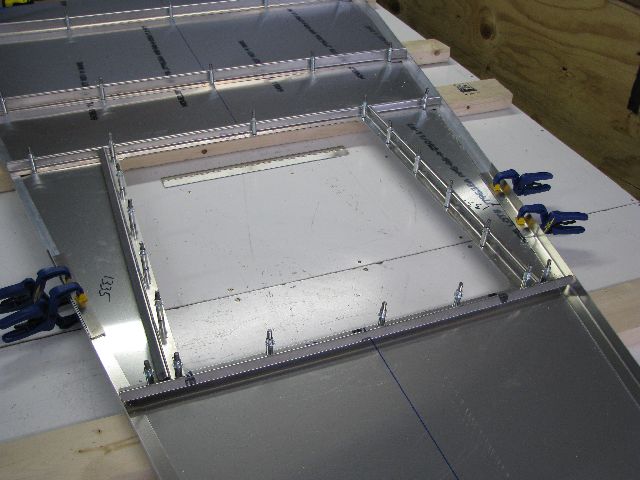
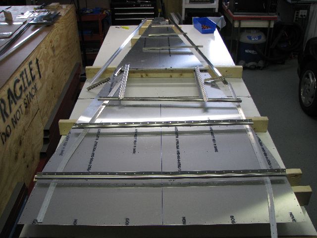
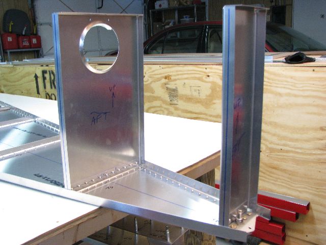
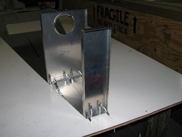 Feb 3, 2010 - Fore & aft HT frames fitted, trimmed & clecoed in place. Eventually, these will provide support
for the Horizontal Stabilizer.
|
 Feb 7, 2010 - Added "L" & "Z" angles to bottom skin as part of structure support.
|
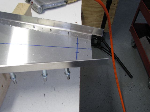
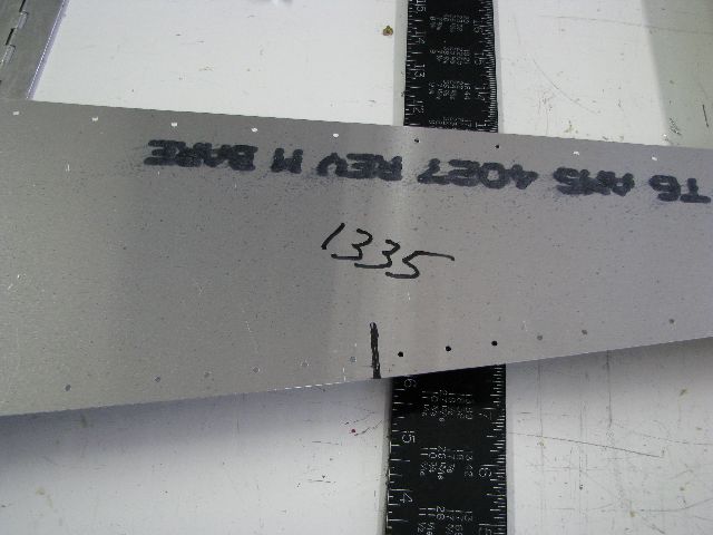 Feb 9, 2010 - A mark is drawn 1335 mm from the front edge, on each side of the bottom skin. The mark is adjusted slightly
to lay at a mid point between two rivets. This is the splice point between the front and rear longerons.
|
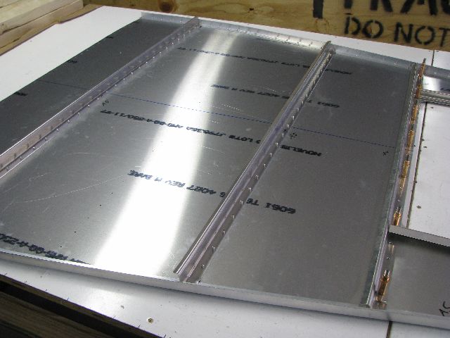
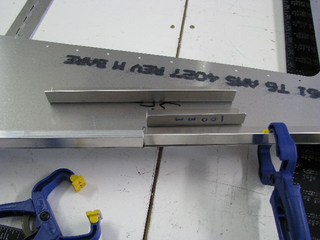 Feb 9, 2010 - Front & rear longerons, 100 mm shim for rear longeron, and 200 mm splice.
|
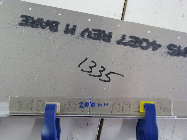 Feb 9, 2010 - Shim and splice in place ready to drill. The shim doubles the thickness of rear longeron to match the
heavier front longeron.
|
 Feb 9, 2010 - All "L" and "Z" pieces trimmed to fit between longerons.
|
 Feb 9, 2010 - Add "Z" angles to sides of access door. (Opening is square, looks otherwise due to camera angle.)
|
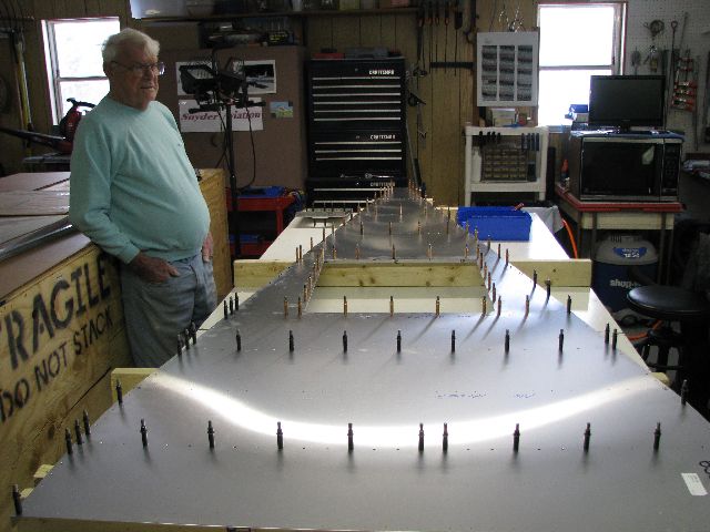
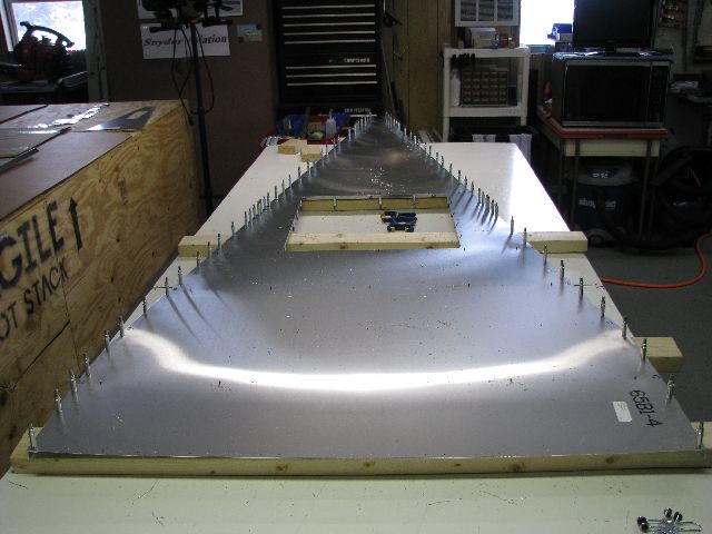 Feb 9, 2010 - Bottom skin flipped over, and longerons drilled and clecoed to skin.
|
 Feb 9, 2010 - View of tail. Rear longerons will be trimmed after later steps.
|
 Feb 9, 2010 - View of longeron splice point.
|
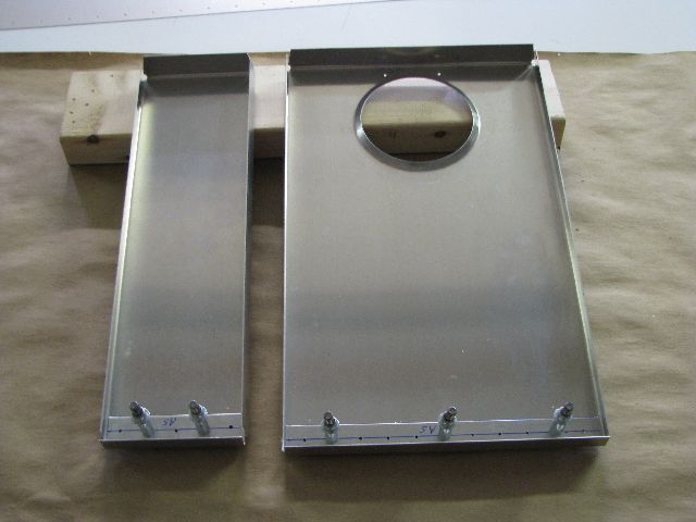
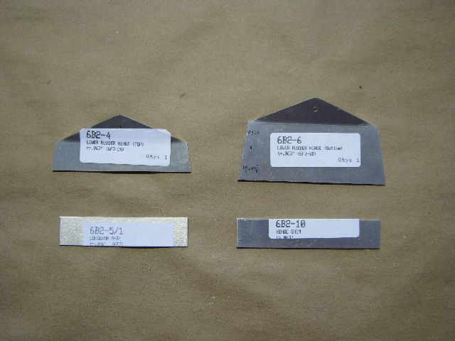 Feb 10, 2010 - Top & bottom lower rudder hinge brackets, and shims
|
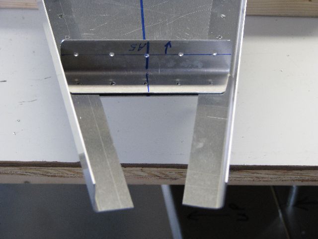 Feb 10, 2010 - Rear Horizontal Tail Bracket (with upper portion removed for easier installation).
|
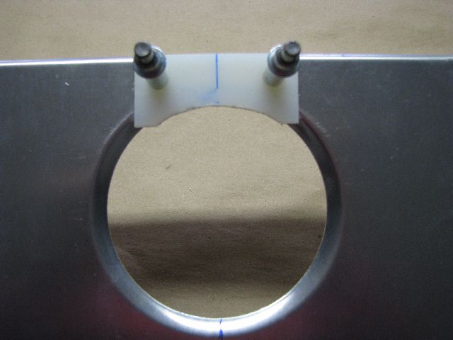
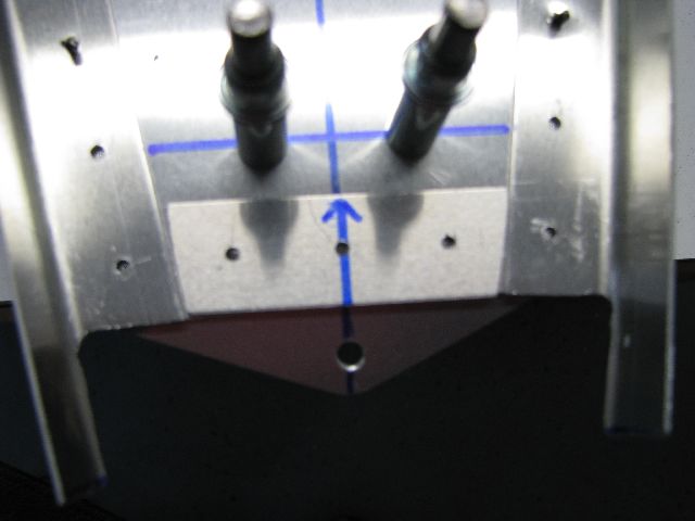
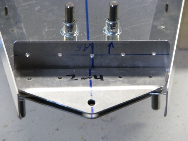
 Feb 10, 2010 - HT bracket removed. Rivet line marked for bottom hinge bracket.
|
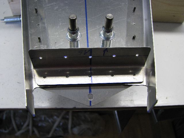
 Feb 10, 2010 - Bottom hinge bracket clecoed in place.
|
 Feb 10, 2010 - Shim trimmed and placed between longerons.
|
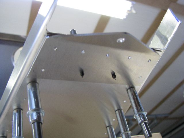
 Feb 10, 2010 - The HT bracket sits on top of the shim.
|
 Feb 10, 2010 - Next is a heavier shim on top of the HT bracket.
|
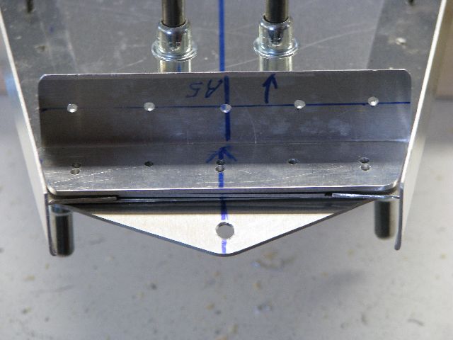
 Feb 10, 2010 - Finally, the top lower hinge bracket is put in place.
|
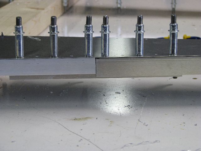
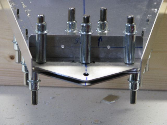 Feb 10, 2010 - The complete assembly clecoed in place.
|
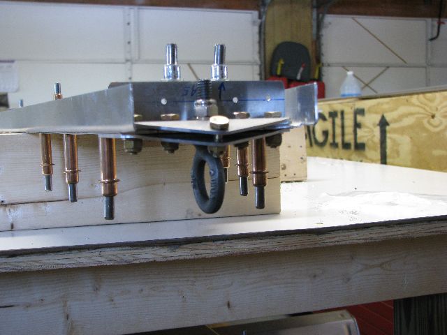
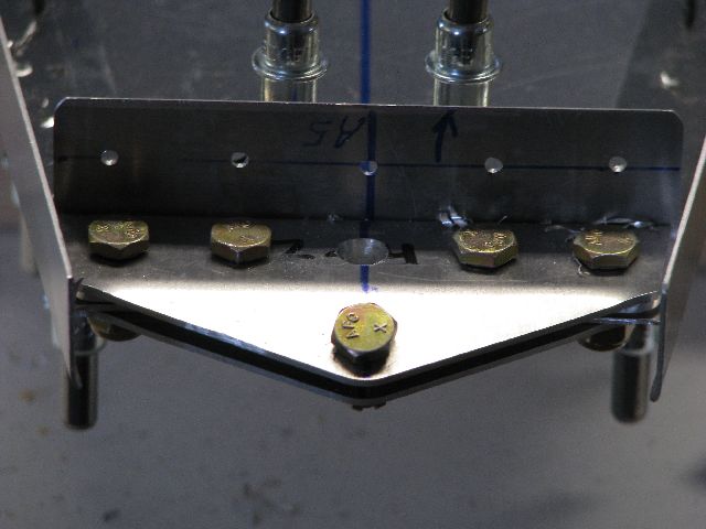 Feb 10, 2010 - 3/16 bolts are used instead of rivets. The bolt in front center uses a spacer between the top and bottom
hinge brackets.
|
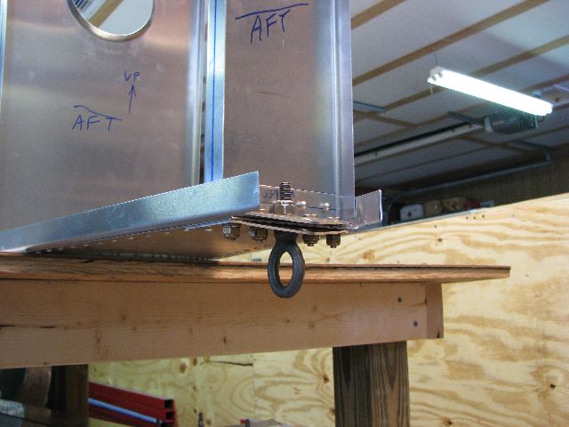
 Feb 10, 2010 - The back center hole is 5/16 and is for the tail tie down ring.
|
 Feb 20, 2010 - Disassembled bottom skin components for deburring.
|
 Feb 20, 2010 - Components deburred and reassembled, ready for riveting. Clay Heathco feeling well enough to come over
and help.
|
 Feb 20, 2010 - Rear fuselage bottom skin riveted, showing outside of skin. This side will be facing down when aircraft
completed.
|
 Feb 20, 2010 - Inside of bottom skin, facing in final position. Front of access door left un-riveted at this point.
|
 Feb 20, 2010 - Horizontal Tail Frames riveted in place.
|
 Feb 20, 2010 - Lower rudder hinge bracket and tie down ring bolted in place. Bolts will be torqued during final assembly.
|
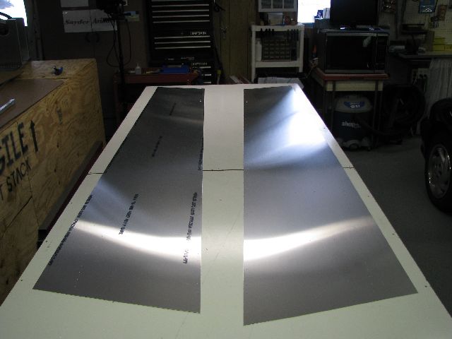 Feb 21, 2010 - Rear side skins. Marked left & right sides, and did layout work for stiffeners.
|
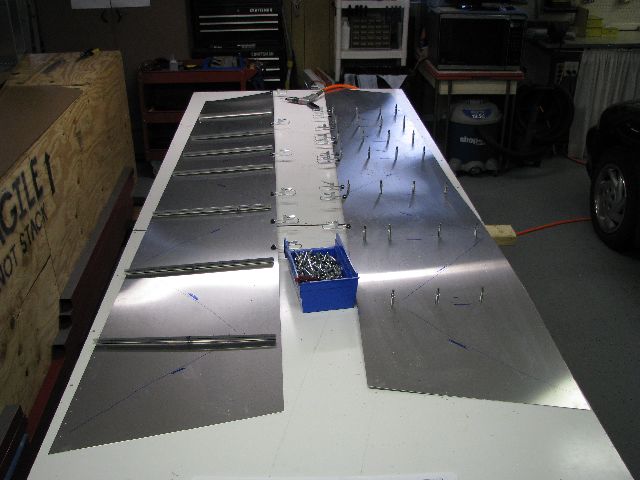 Feb 22, 2010 - Right side skin (on left in pic) with rough cut "L" angles laid on top prior to drilling. Pilot
side skin (on the right) clecoed.
|
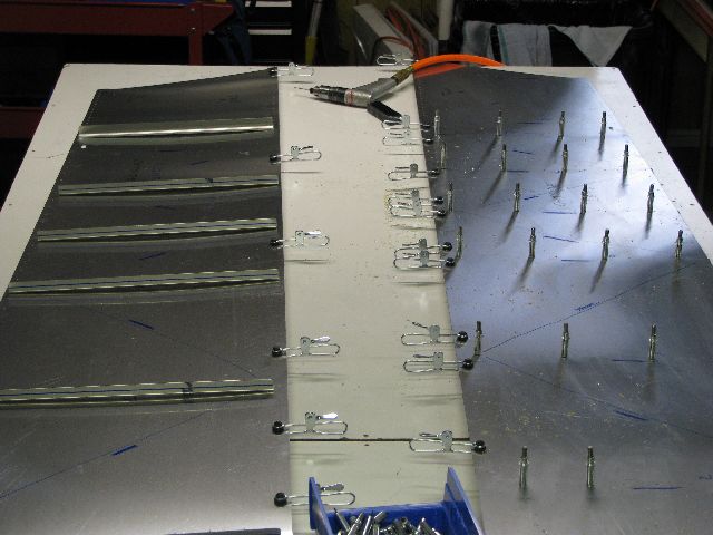 Feb 22, 2010 - Closer view showing rough lines where diagonal stiffeners will go. Heavy marks indicate which side the
bend will be.
|
 Feb 22, 2010 - Inside view of right & pilot side skins with vertical "L" angle stiffeners clecoed in place.
|
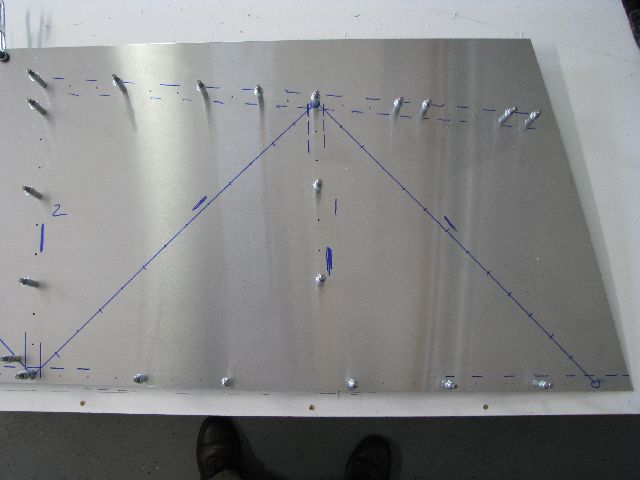 Feb 24, 2010 - Laid out drill patterns for diagonal "L" stiffeners for both side skins.
|
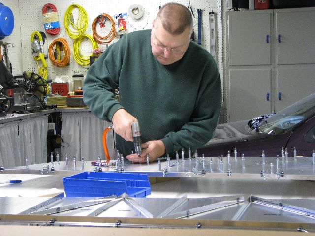 Feb 27, 2010 - Drilling diagonal stiffeners on pilot side rear skins.
|
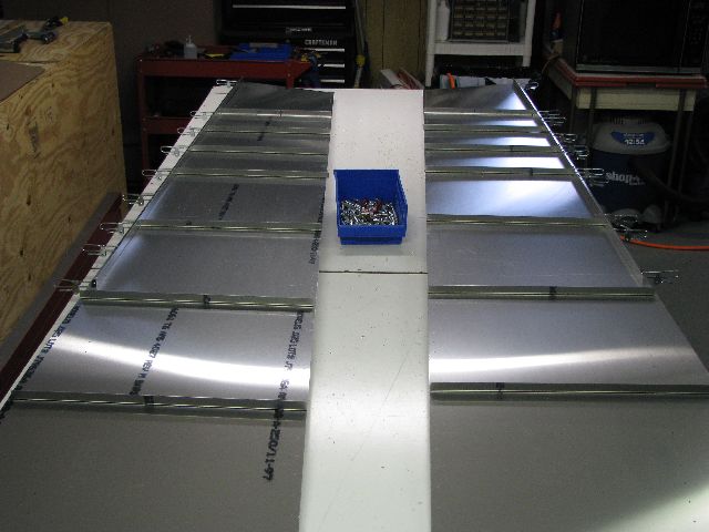
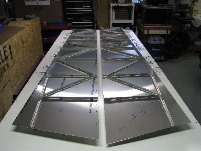 Feb 27, 2010 - Both sides with all stiffeners clecoed in place.
|
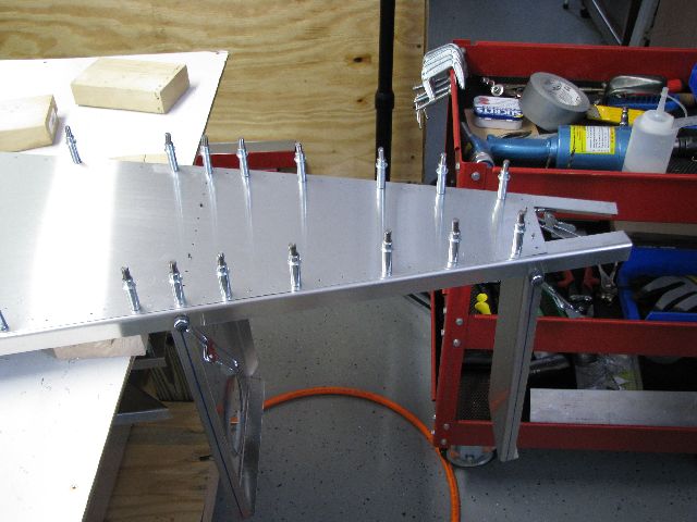
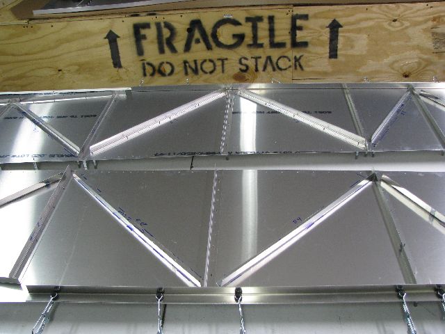 Feb 27, 2010 - Side view of stiffeners. Note top longerons only clamped in place at this time.
|
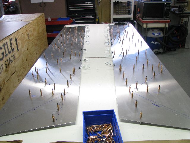 Feb 28, 2010 - Trimmed all "L" angles to final size and drilled out to final A4 size. Won't rivet until sides
mated to bottom skin and final alignment.
|
|
Enter supporting content here |