|
 June 30, 2010 - Drilled and clecoed aileron to the wing. |
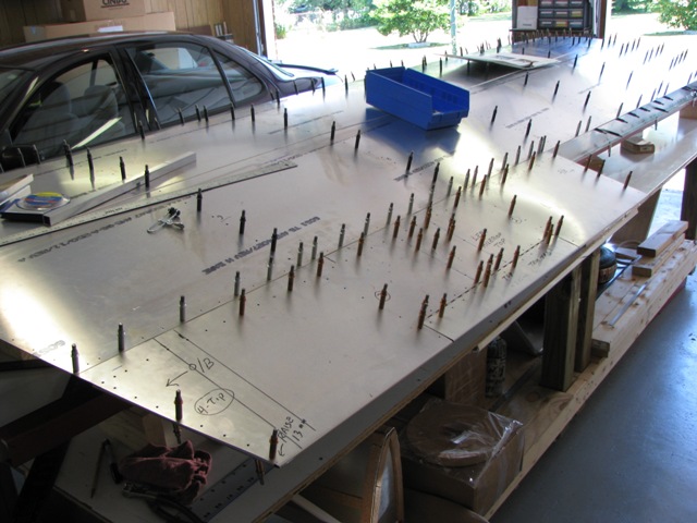
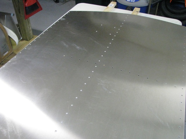
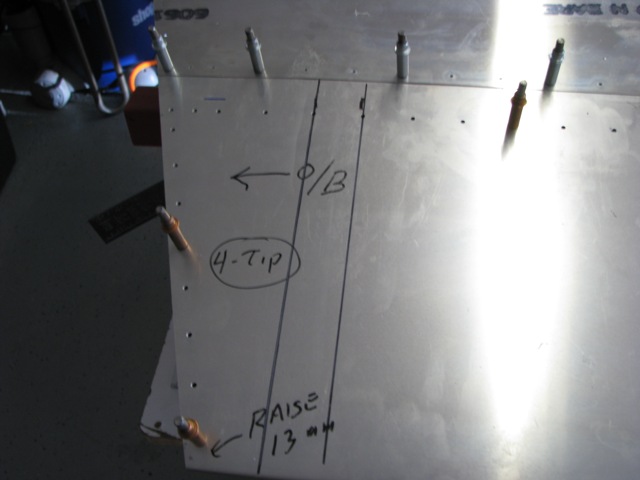 Jun 30, 2010 - Marked aileron for insertion of mass balance ribs as part of upgrade.
|
 Jun 30, 2010 - Marked aileron for insertion of mass balance ribs.
|
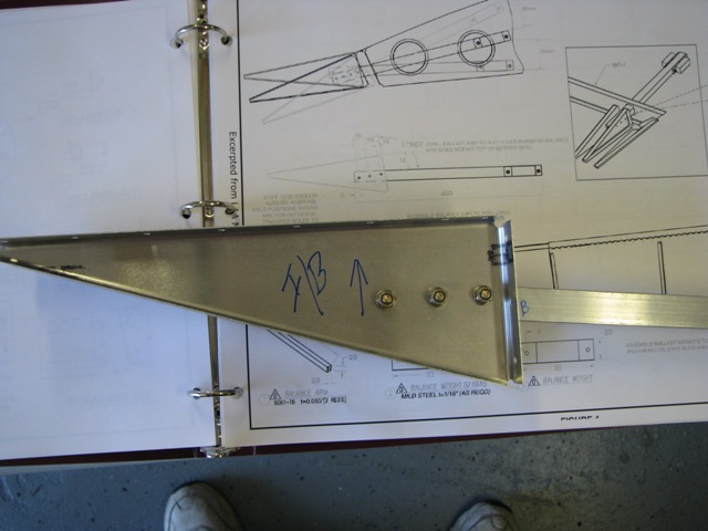
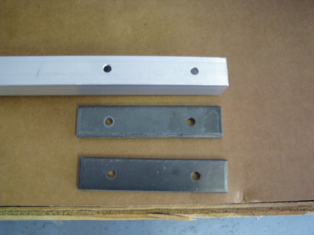
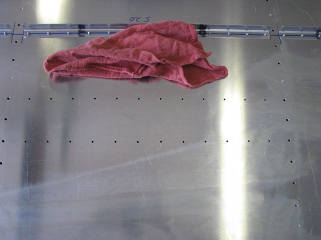
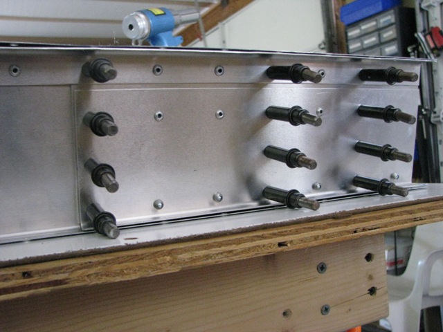
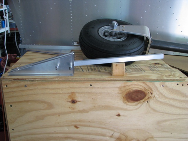 Jul 2, 2010 - Drilled MB ribs and weight arm. Arm is 97 degrees from front face of ribs. (Shown in upside down position.)
|
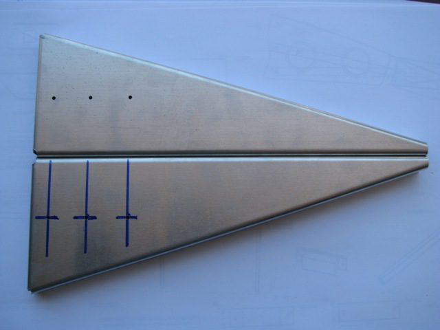
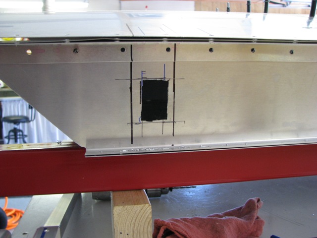
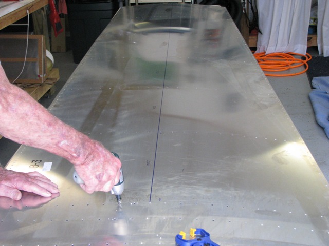
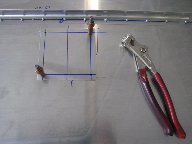
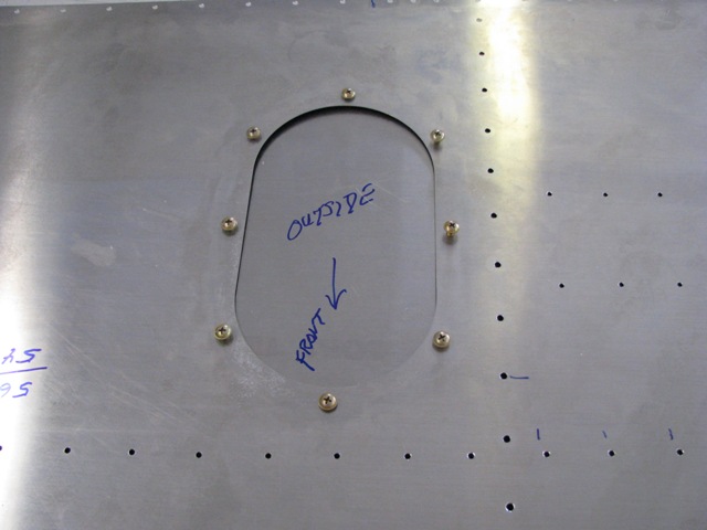
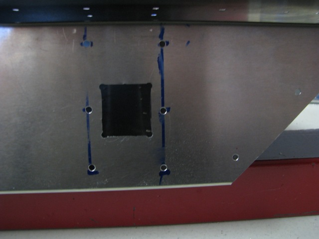 Jul 2, 2010 - Cut square opening in face of aileron for MB arm.
|
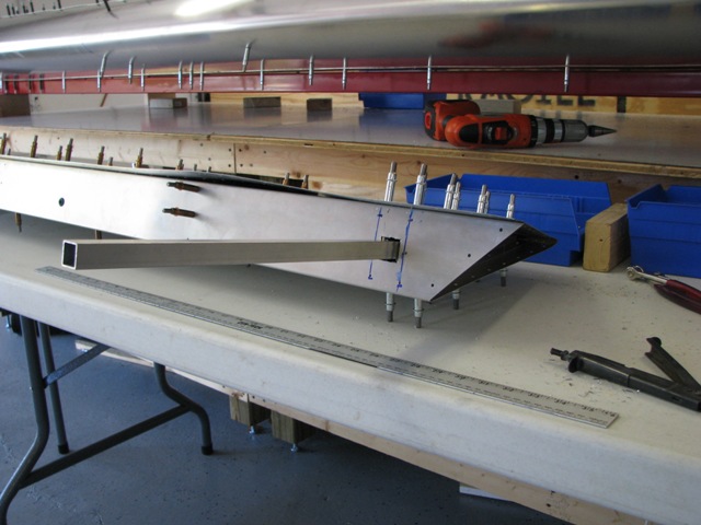
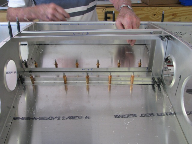
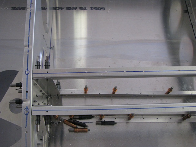
 Jul 2, 2010 - Inserted MB ribs and arm, and drilled at previously determined rivet locations.
|
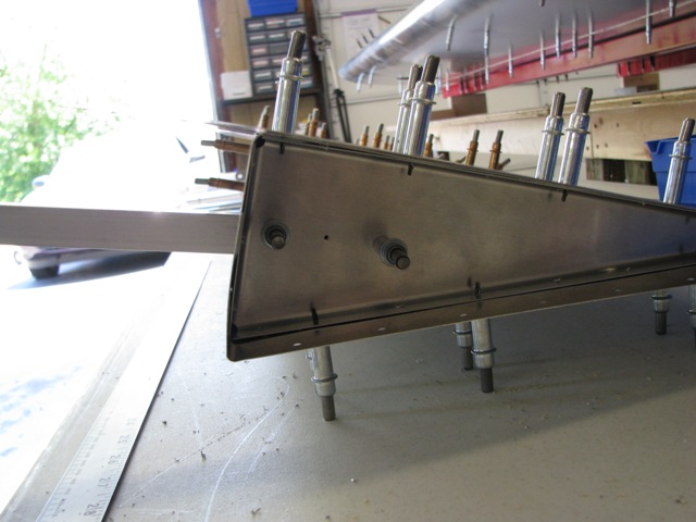
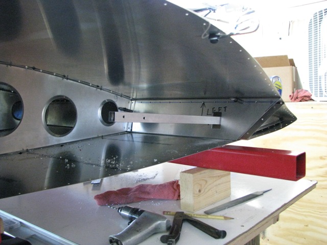
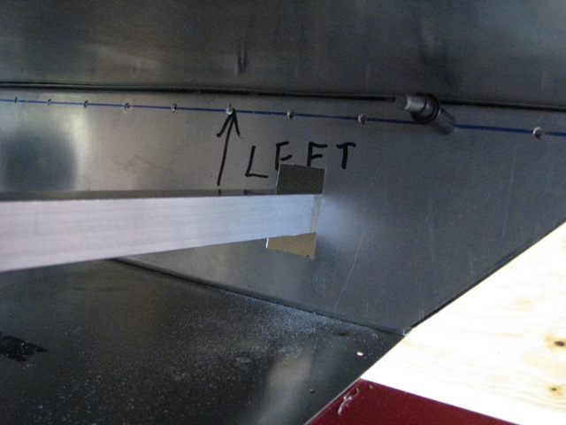
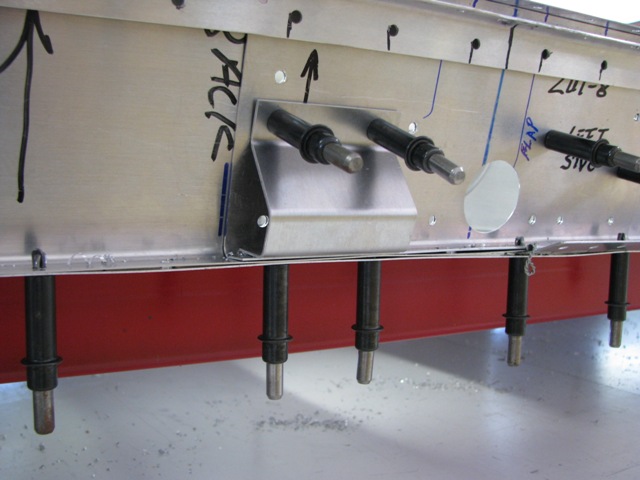
 Jul 2, 2010 - Another angle of MB arm protruding from aileron. This will extend into rear of wing tip.
|
 Jul 2, 2010 - MB ribs and arm joined with AN3 bolts.
|
 Jul 3, 2010 - Drilling 3/16" holes in MB arm for attaching steel weights.
|
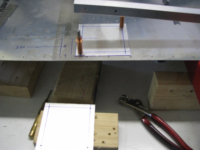
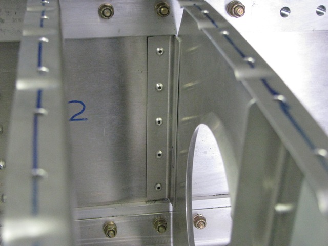
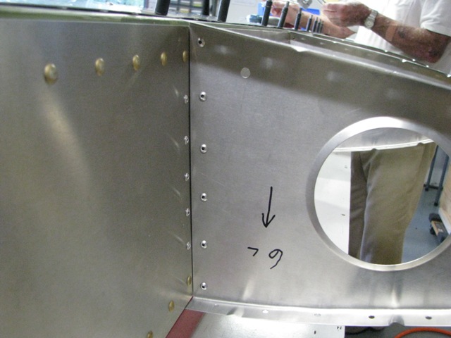
 Jul 3, 2010 - Cutting square hole into rear spar where the MB arm will enter the wing.
|
 Jul 3, 2010 - Aileron clecoed onto wing with mass balance arm extending into wing. The two holes at the end are where
the steel weights will attach.
|
 Jul 3, 2010 - Closer look at the square entry hole after trimmed and cleaned up. Must be large enough to allow ample
up and down movement.
|
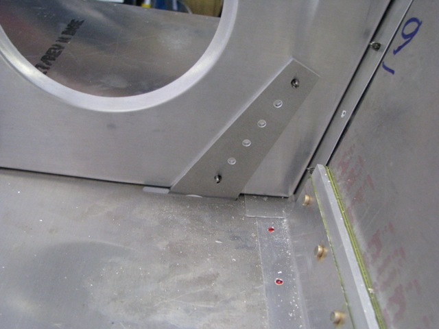
 Jul 5, 2010 - Added aileron stop to rear spar.
|
 Jul 5, 2010 - Clay Heathco helping remove top and nose skins for deburring.
|
 Jul 6, 2010 - Bottom skin bell crank L-angle supports drilled out to final size. Top skin support angles will be drilled
later.
|
 Jul 6, 2010 - Bell crank assy. Drilled out to A5 size.
|
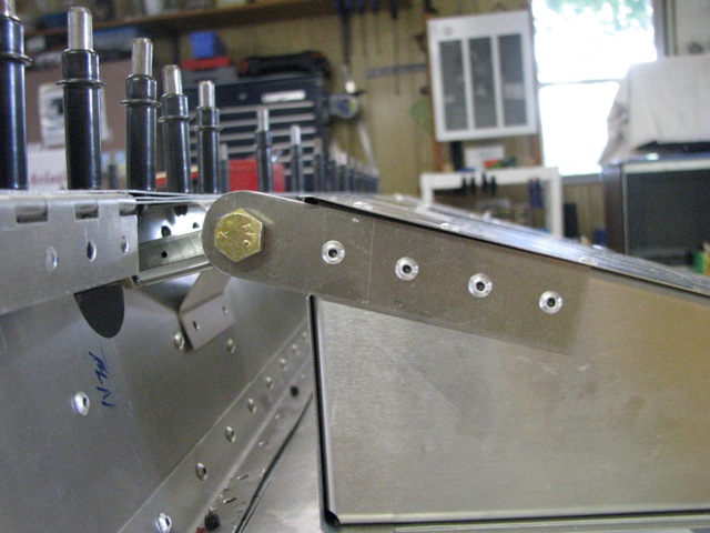
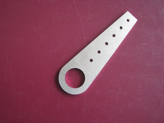 Jul 7, 2010 - Wing tie down ring.
|
 Jul 7, 2010 - Tie down ring clecoed to Rear rib #9 (outboard end of wing).
|
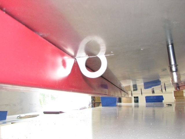 Jul 7, 2010 - Tie down ring protruding through slot in bottom skin.
|
 Jul 8, 2010 - Positioned reinforcing "bang plate" inside end of wing below mass balance arm where weights will attach.
|
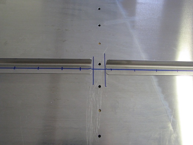
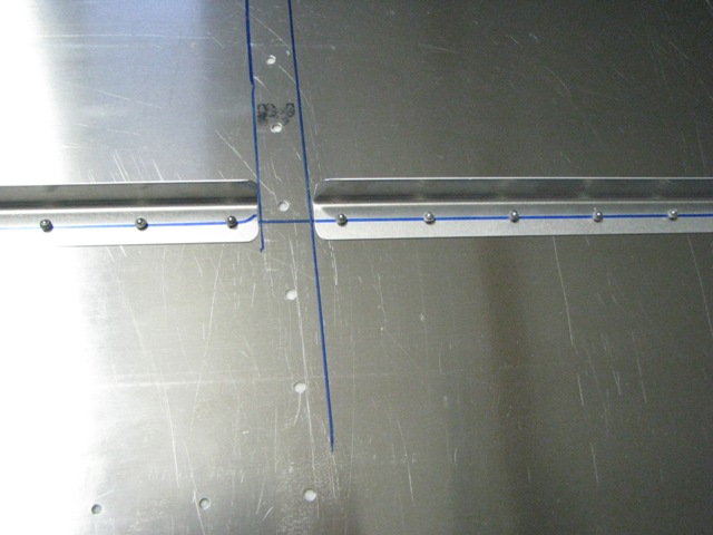
 Jul 10, 2010 - Blue longitudinal line indicates where reinforcing L-angles will be attached under top skin.
|
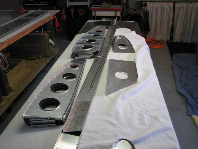
 Jul 10, 2010 - Cut and marked L-angles to fit between each rear rib.
|
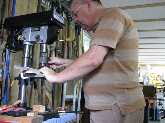 Jul 10, 2010 - Received drill press for Fathers Day. Came in handy to drill L-angles accurately.
|
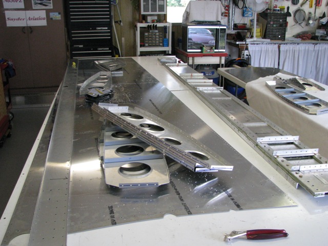
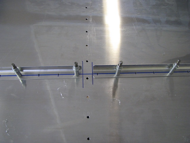 Jul 10, 2010 - Reinforcing L-angles drilled and clecoed to underside of left wing top skin.
|
 Jul 11, 2010 - Checked L-angle stiffeners for fit with ribs, then riveted.
|
 Jul 11, 2010 - Drilled bell crank L-angles and top skin, and deburred.
|
 Jul 11, 2010 - Wing top skin showing rivet lines for bell crank L-angles.
|
 Jul 11, 2010 - Drilled mass balance "bang plate" to top skin.
|
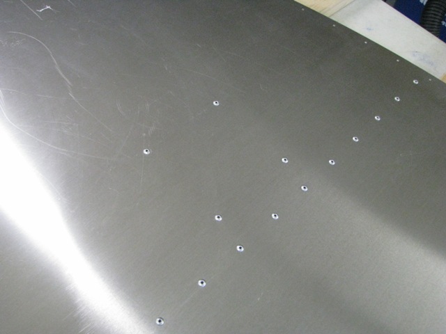 Jul 11, 2010 - Riveted mass balance "bang plate" to top skin.
|
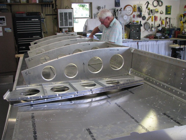 Jul 11, 2010 - Clay Heathco deburring top of main spar while I start disasssembling ribs.
|
 Jul 11, 2010 - Disassembly complete. Now the fun of deburring all those holes (both sides).
|
 Jul 12, 2010 - All ribs, rear spar, and other goodies deburred. Deburring bottom skin is next.
|
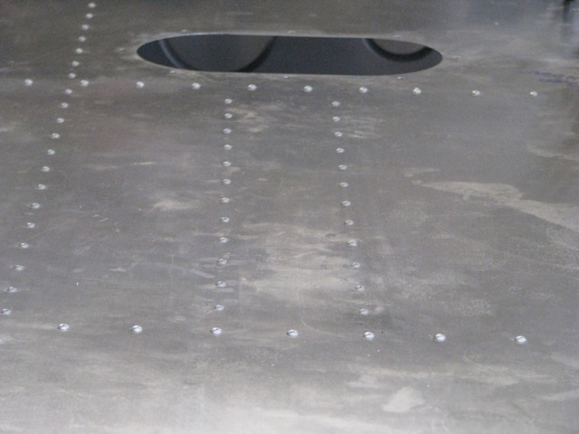
 Jul 13, 2010 - Added nut plates to bell crank access cover, and positioned on bottom skin. Also visible are drilled
holes for bell crank support L-angles and longitudial bottom wing stiffeners.
|
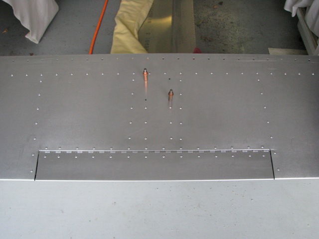 Jul 14, 2010 - Finished riveting left aileron. Clecos hold trim servo unit. Will leave this way until final assembly
in case changes needed.
|
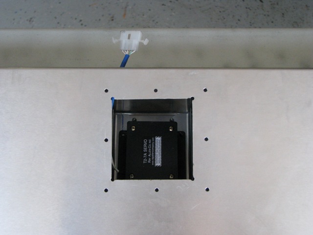 Jul 14, 2010 - View of trim servo and molex wiring connector.
|
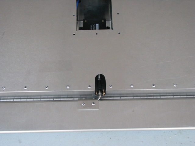 Jul 14, 2010 - Servo control rod attached to trim tab.
|
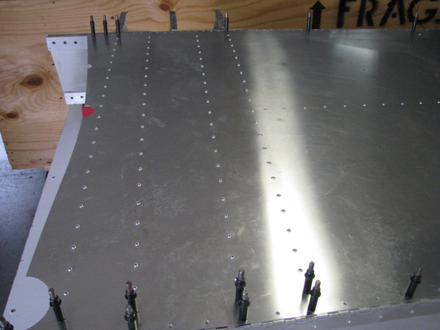
 Jul 15, 2010 - Riveted L-angle stiffeners to inside of bottom skin.
|
 Jul 15, 2010 - Riveted L-angle reinforcements, root end doubler plates, and aileron control rod doubler to rear spar.
|
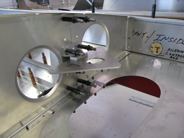
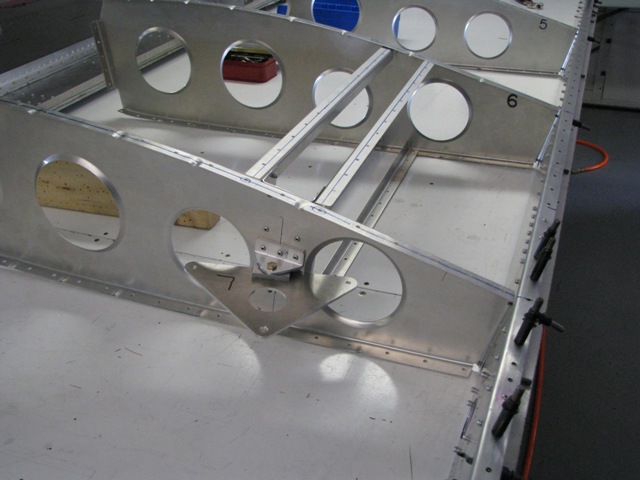 Jul 15, 2010 - Riveted bell crank assembly and support angles to rear rib #7.
|
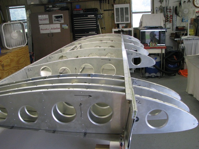
 Jul 15, 2010 - Riveted rear ribs to main spar.
|
 Jul 15, 2010 - Ribs #1 & #4 must be riveted from inside due to interference with new upright supports added to new factory
spar.
|
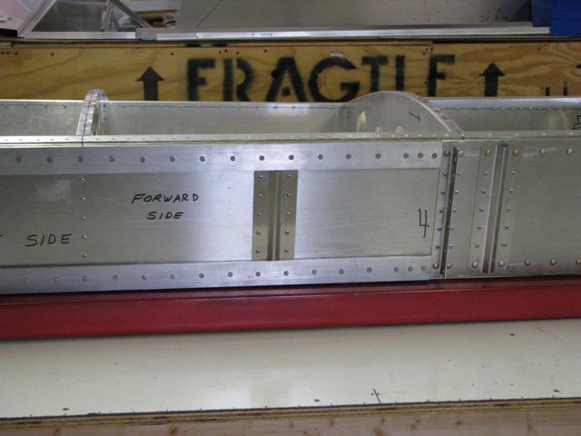
 Jul 16, 2010 - Riveted rear ribs to rear spar.
|
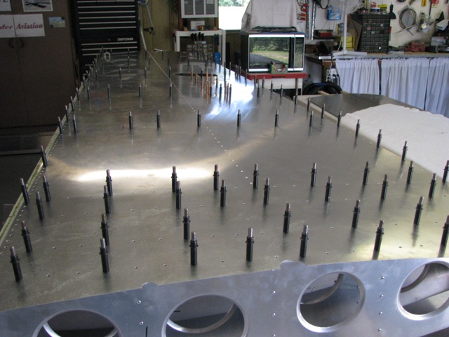 Flipped skeleton upside down, and clecoed bottom skin to skeleton.
|
 Jul 18, 2010 - Riveted control rod horn to left aileron. Tested location of control rod. Needed to enlarge hole
to accommodate rod end.
|
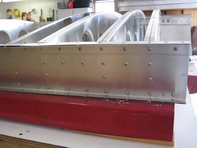
 Jul 18, 2010 - Riveted bottom skin to skeleton. Leading edge left clecoed until nose skin attached. Flap hinge
also left clecoed only.
|
 Jul 18, 2010 - Bell crank support L-angles rivetd to bottom skin.
|
 Jul 18, 2010 - Nose ribs riveted to main spar.
|
 Jul 18, 2010 - Wing assembly flipped over (top side up) in prep for next steps.
|
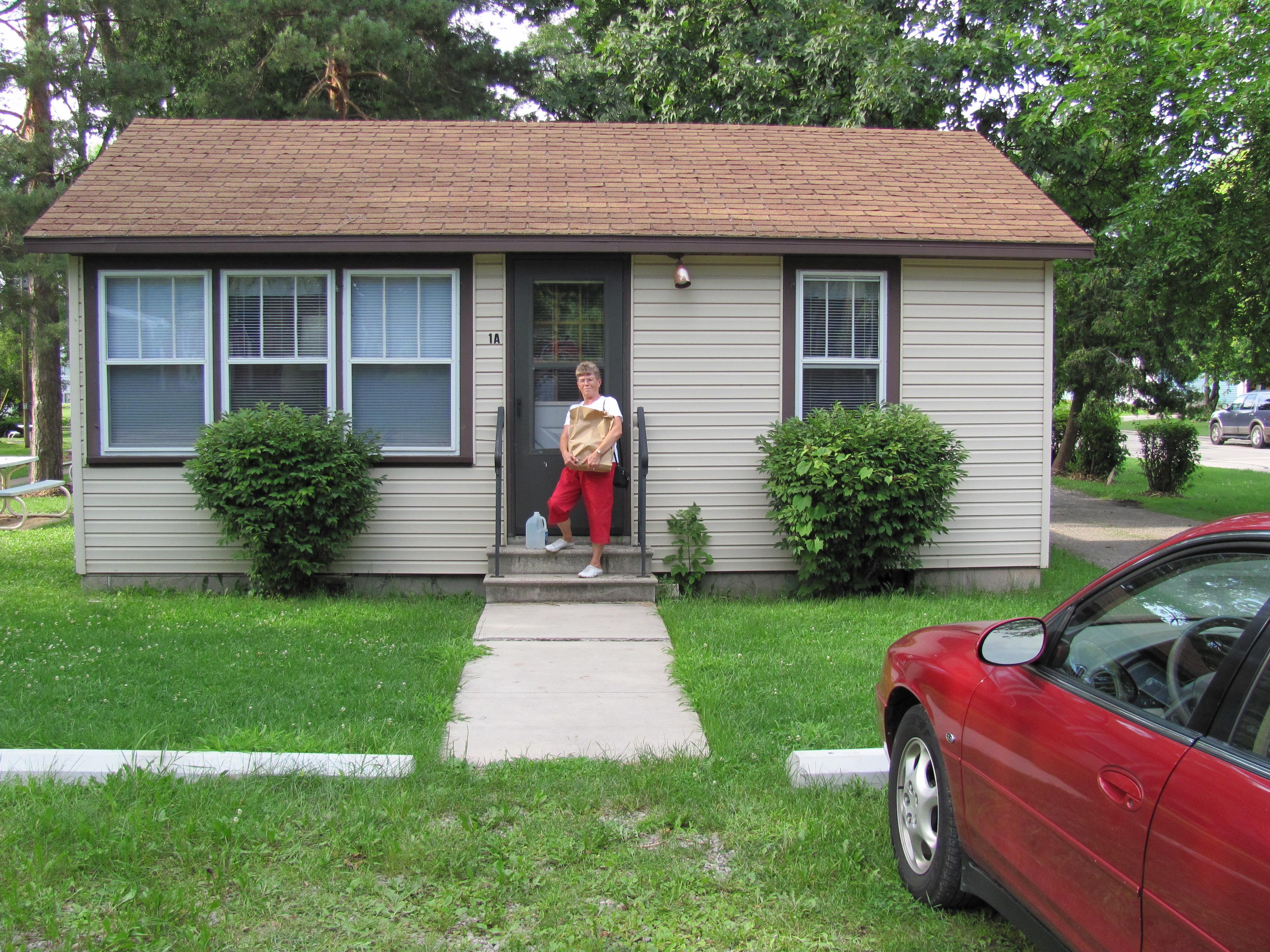 Jul 26, 2010 - Off to Oshkosh for EAA. The cabin we rented in Winneconne.
|
|
Enter supporting content here |