|
Enter subhead content here
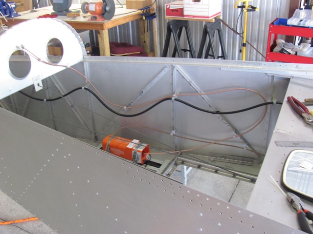
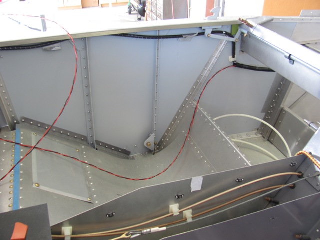
Jun 25, 2019-The ELT coax now relocated to the left side so that it is secure
and does not interfere with any control cables.
Jun 28, 2019- Removed panel top cover to get the ELT remote.
Jun 28, 2019-Removed the old Ameri-King remote and installed the
new
ACK remote in the panel.
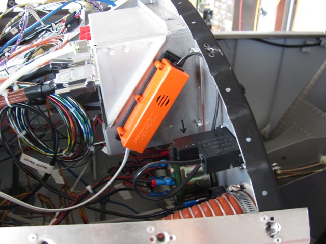
Jul 2, 2019-Used Velcro to attach the ELT audio alert to the panel.
Jul 15, 2019-I am installing a TailBeacon ADS-B out unit by Avionix.
Feeding wire for the ADS-B unit through existing conduit.
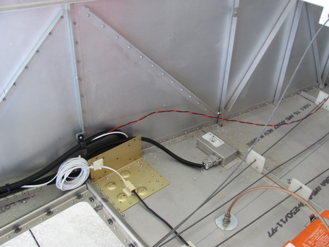
Jul 15, 2019-ADS-B wire coming out back of conduit. Will need spiral
wrap to finish run to tail.
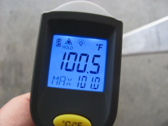
Jul 15, 2019-Laser thermometer shows 100.5 to 101.0 degrees. Time to go home.
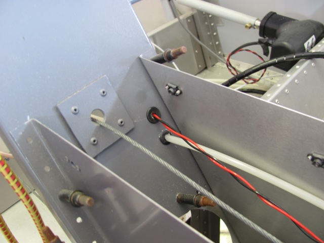
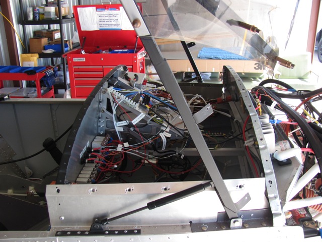
Jul 23, 2019 - Realized that running electrical current through the same
conduit as that carrying the remote compass cable was not a good idea.
Rerouting
ADS-B wire through the center console.
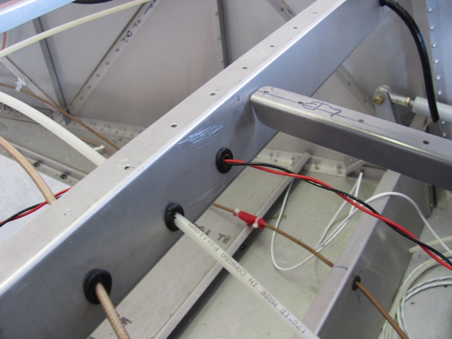
Jul 23, 2019-Routing the ADS-B wire through the baggage floor support.
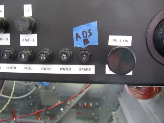
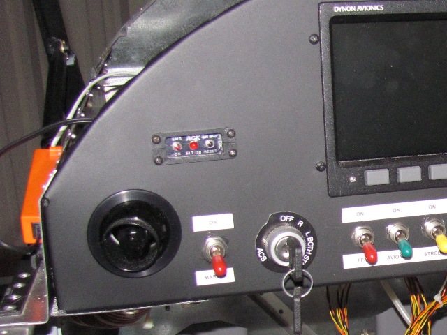
Jul 24, 2019-Replaced the 7 1/2 A circuit breaker with a 3A breaker for
the TailBeacon ADS-B out/nav light. The LED system only pulls 3 watts.
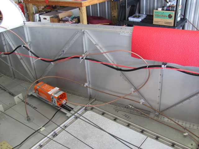
Jul 24, 2019 - The ADS-B wiring will be under the baggage floor and
along
the left side of the airframe. I used the existing elevator trim
conduit as support
for the ADS-B wiring.
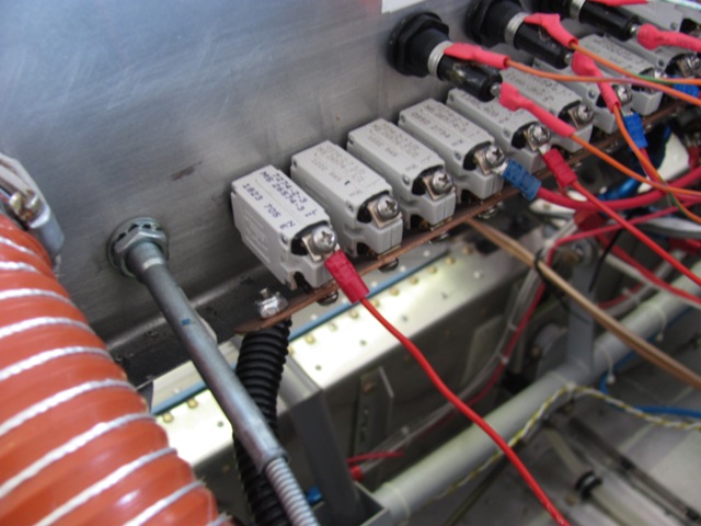
Jul 24, 2019 - Breaker on the left is the new ADS-B. Checked functionality.
Power to the tail, and beaker on/off works.
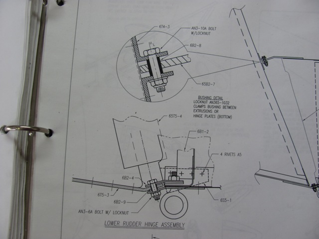
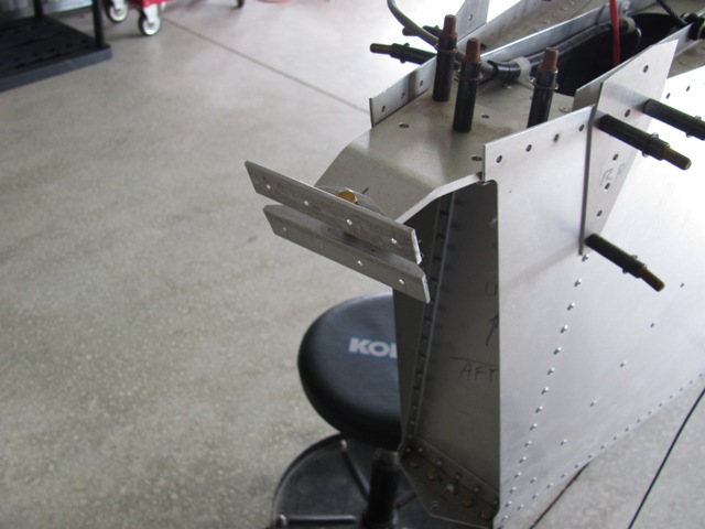
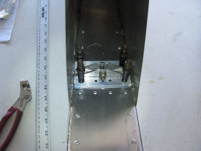
Jul 26, 2019 - Details of the upper and lower rudder hinges.
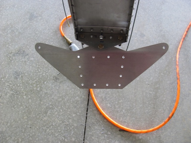
Jul 26, 2019 - Lower rudder support dry fit. (Later realized it was upside
down, but was testing bushing fit, so OK.)
Jul 29, 2019 - Lower hinge bracket clecoed to bottom of rudder.
Jul 29, 2019 - Mark on rudder according to plans where upper hinge
is
to be mounted, Needs to be verified by actual measurements.
Jul 29, 2019 - Rudder upper hinge bracket dry fit to check measurements.
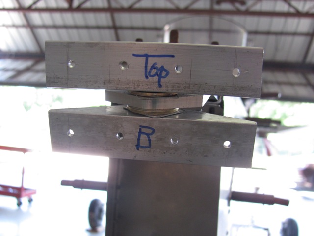
Aug 1, 2019 - Used spacers to "center" the rudder top hinge bracket.
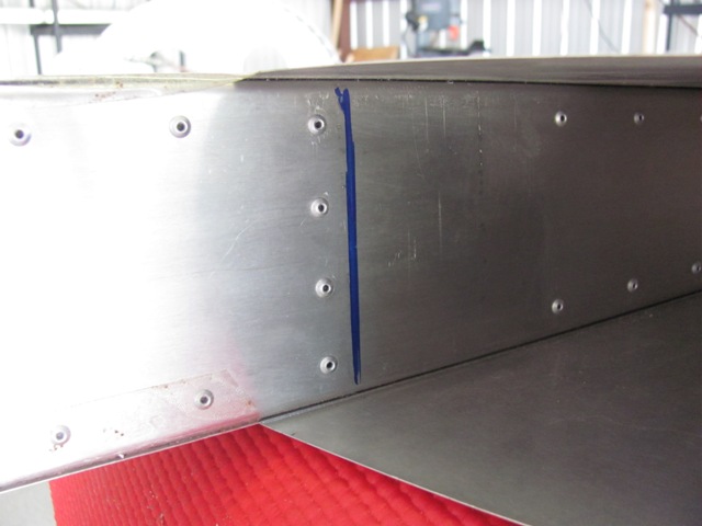
Aug 1, 2019 - After dry fitting the rudder, this mark indicates the
bottom
edge of the bottom bracket.
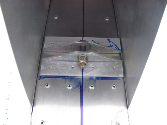
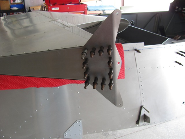
Aug 2, 2019 - The rudder upper hinge bracket in place.
Aug 2, 2019 - The rudder upper hinge drilled out to A5 size and cleco in place.
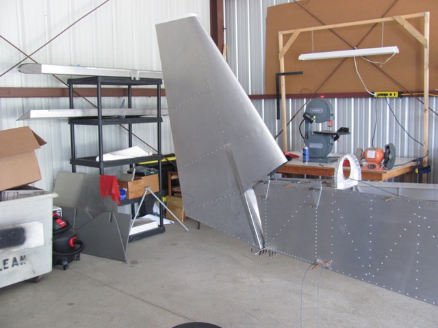
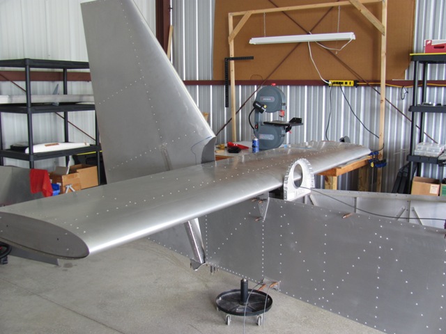
Aug 3, 2019 - The rudder on the plane (with clecoes only).

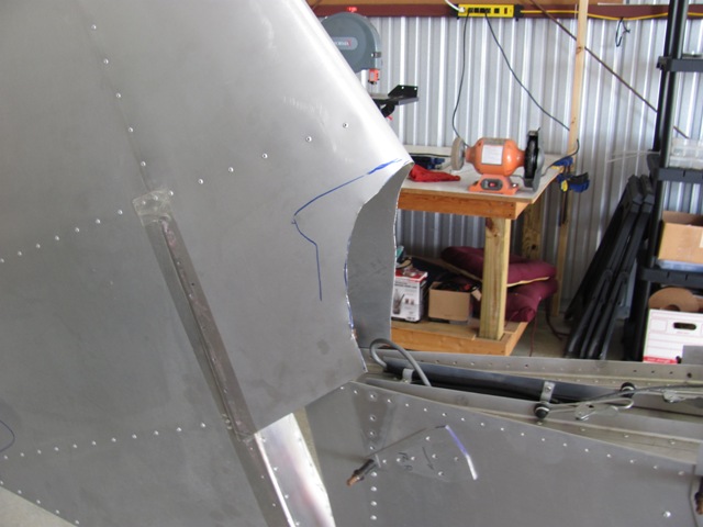
Aug 3, 2019 - Making paper template to start trimming the leading
edge of the rudder.
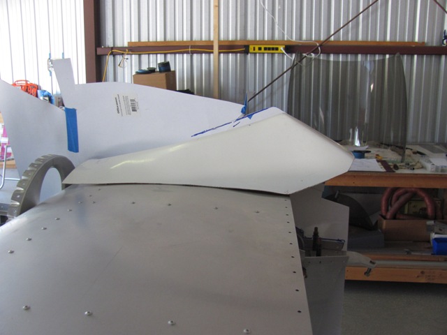
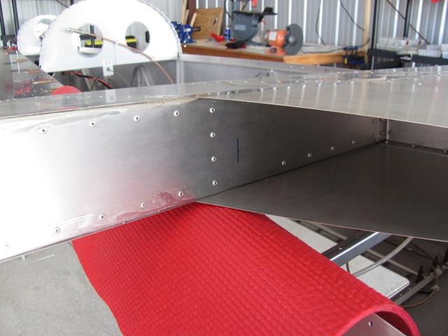
Aug 3, 2019 - Leading edge of rudder must be trimmed to clear this
cover
which protects the elevator cables and horn.
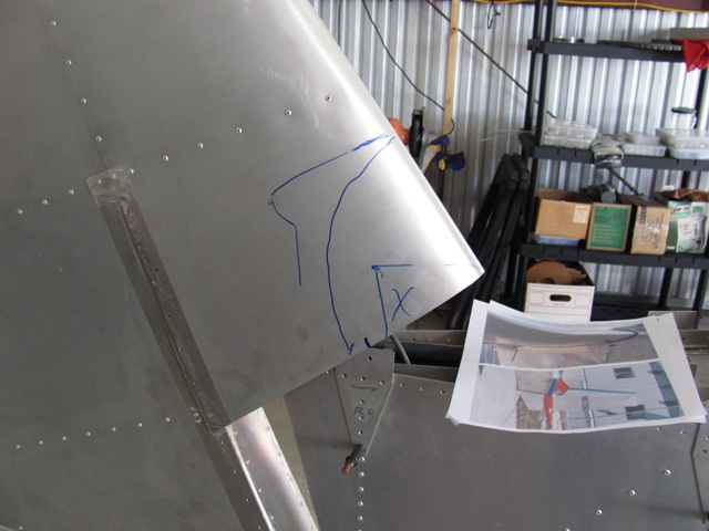
Aug 5, 2019 - Rough cut lines based on my paper template.
Aug 5, 2019 - First conservative cut.
Aug 5, 2019 - Just enough cut to allow horizontal stabilizer to be attached.
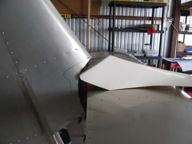
Aug 5, 2019 - The horn cover that has to be cleared.
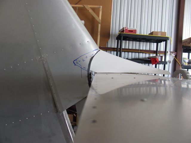
Aug 5, 2019 - The horn cover positioned behind the rudder to indicate
how
much more has to be trimmed.
|
Enter supporting content here |