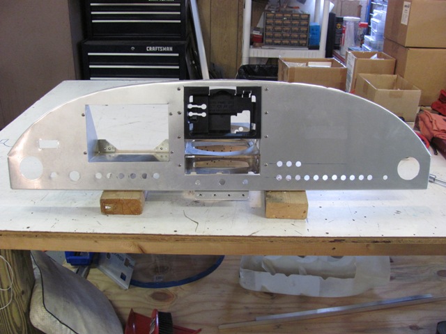
| Feb 3, 2015 - Removed panel and disassembled in preparation for painting. |
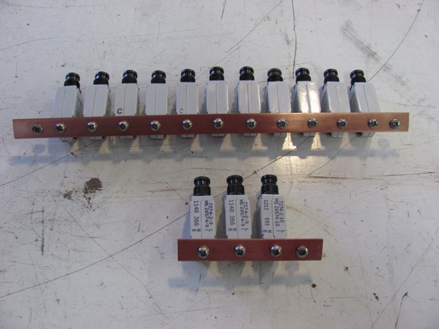
| Feb 3, 2015 - Affixed bus bars to circuit breakers. |
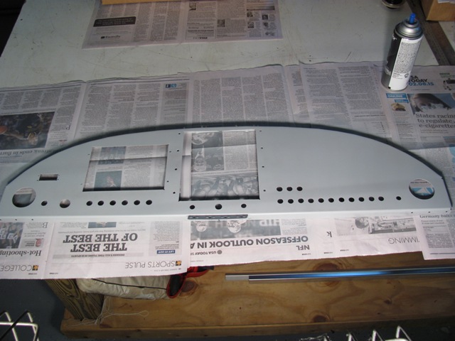
| Feb 12, 2015 - Cleaned and primed panel. Later,
painted with dark gray enamel top coat. |
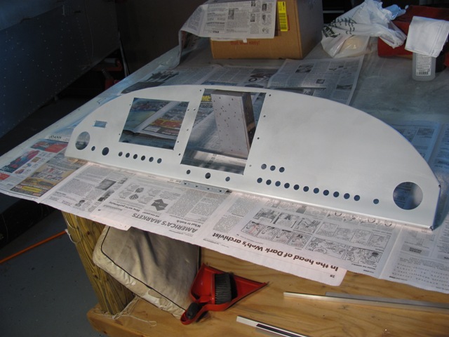
| Feb 28, 2015 - After having painted and repainted the panel three times, I completely stripped it, sanded, primed
and started over with new paint. |
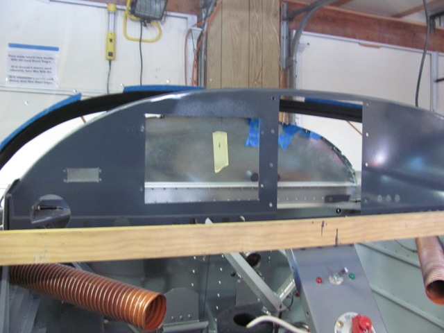
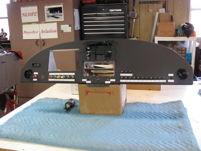
| Feb 28, 2015 - The finished product looks better that what this picture shows, but I am still not happy. |
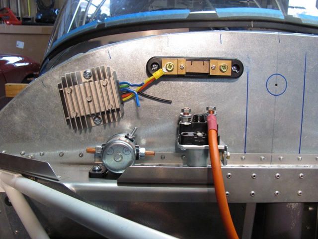
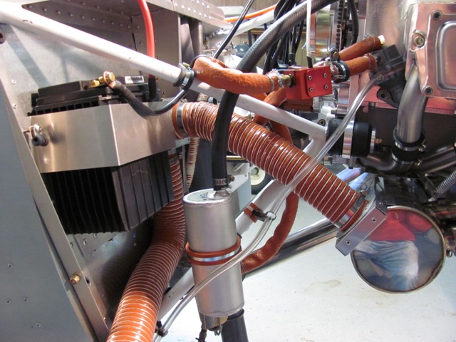
| Mar 3, 2015 - After much consideration, this is the final placement of electrical components on firewall. Bottom left is battery contactor for the master switch, then the starter solenoid. Top left is regulator, then shunt for amp meter.
Ready for wiring. |
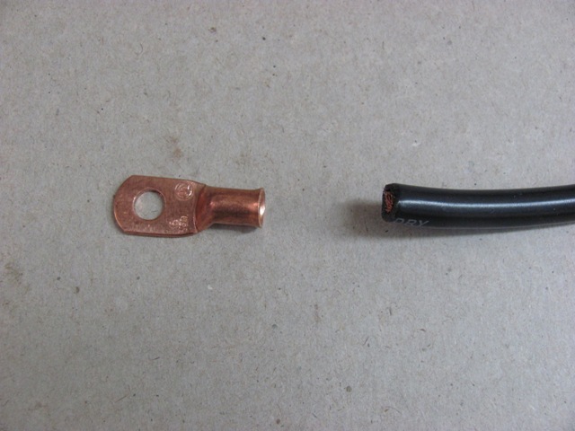
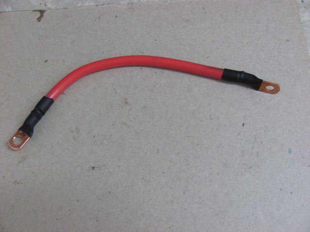
| Mar 4, 2015 - 6 AWG battery cable. Black for ground,
red for hot side. Solder-on copper terminal lugs will be
used after stripping back cable ends. |
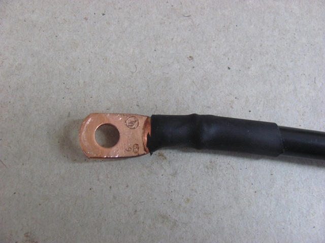
| Mar 4, 2015 - Lug soldered on and covered with shrink wrap. |
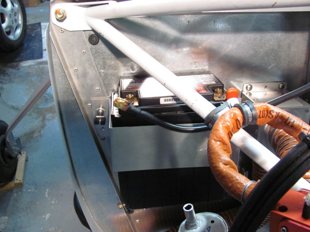
| Mar 4, 2015 - New ground cable attached to battery. |
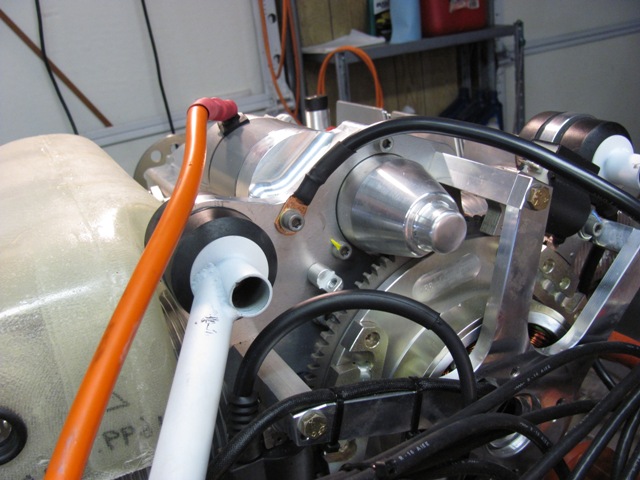
| Mar 4, 2015 - Ground cable attached to engine/starter. |
| Mar 5, 2015 - Fabricating positive battery cable. |
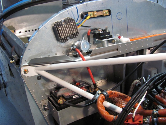
| Mar 5, 2015 - Positive cable installed between battery and master relay. |
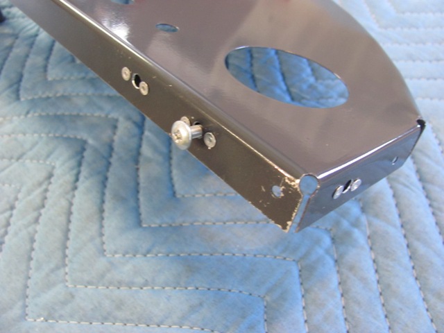
| Mar 6, 2015 - Added nutplates to ends of panel. I
will use only screws to secure panel so it will be removable. |
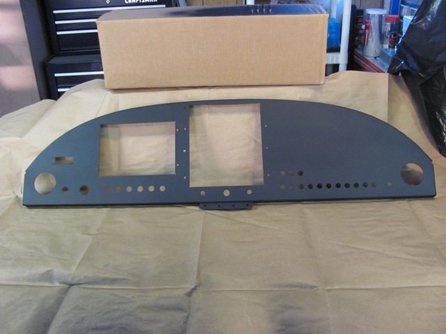
| Mar 6, 2015 - Painted the panel again. This time
flat black. Actual appearance is much better that photo. |
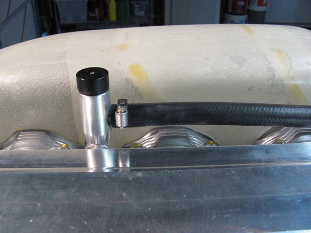
| Mar 9, 2015 - Installed hose for the oil recovery system. A crankcase breather connection built into the dipstick
housing. |
| Mar 9, 2015 - The bottle will catch most oil vapor from the crankcase breather air.
It will be emptied during annual condition inspection. |
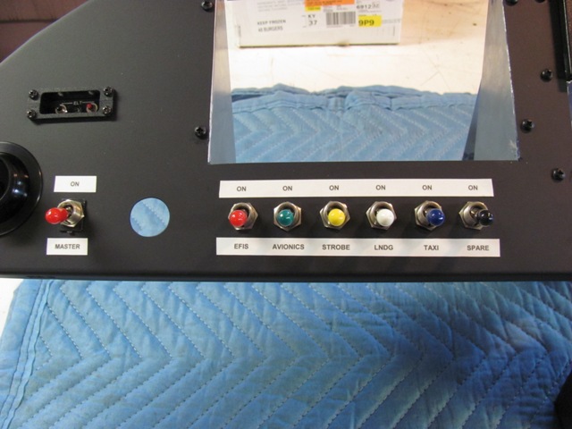
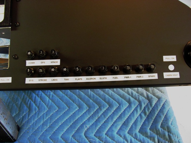
| Mar 11, 2015 - Made labels for panel items. |
| Mar 11, 2015 - Main switches. |
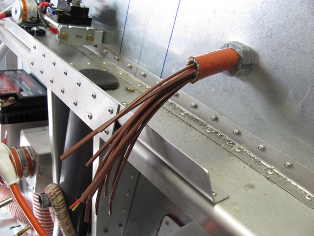
| Mar 16, 2015 - EGT and CHT sensor wiring, Still
room for another dozen sensor leads. |
| Mar 11, 2015 - Circuit breakers. |
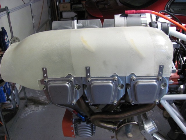
| Mar 17, 2015 - Attached hold down tabs to the engine cooling ducts. Rivets were pulled from inside to provide as much clearance as possible for the cylinder fins. |
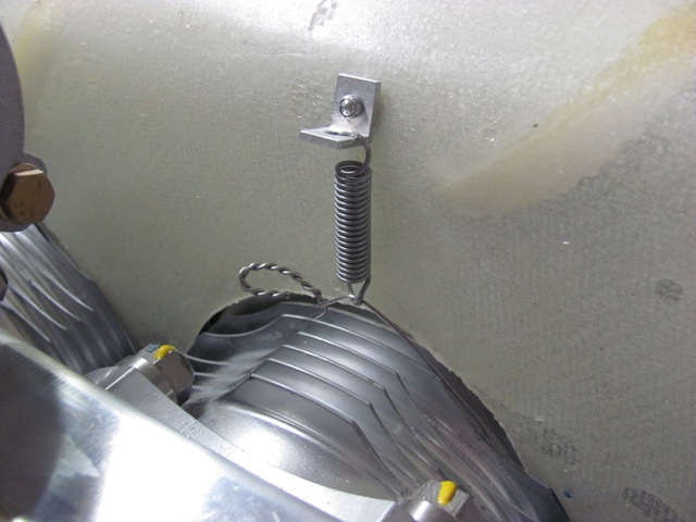
| Mar 17, 2015 - The interior side is secured by running
safety wire around the center cylinder, then attaching to a tab via a spring. | | Mar 21, 2015 - Jabiru issued AVDALSR085-1 modifying location of CHT sensor. This required drilling and tapping for an #6 or #8 screw. I chose #8-32. |
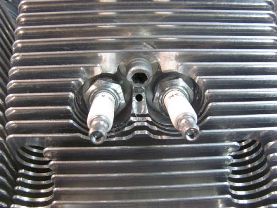
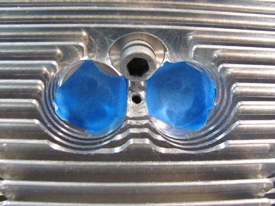
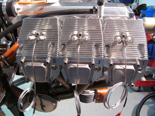
| Mar 21, 2015 - Preparing the section between the spark plugs for the CHT sensors.
The factory supplied a 1/8 inch hole to start. |
| Mar 21, 2015 - Ground down some of the center fin area to provide clearance for the sensor. Drilled and tapped the hole
for 8-32 screw. |
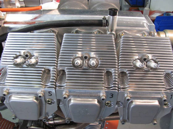
| Mar 21, 2015 - The right bank of cylinder tapped and ready for the sensors. |
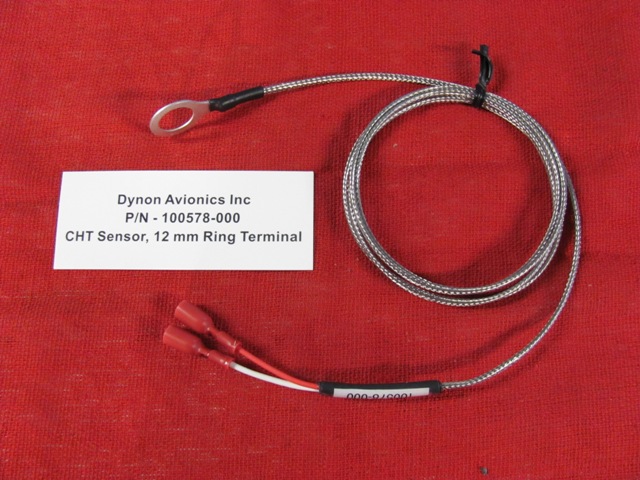
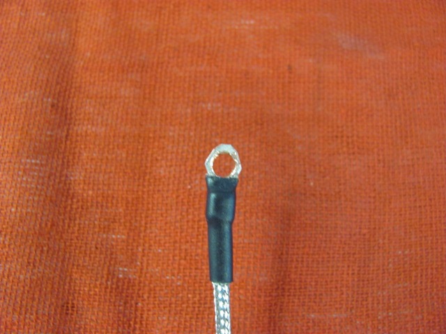
| Mar 26, 2015 - The original CHT sensor with 12mm spark plug lead ring, |
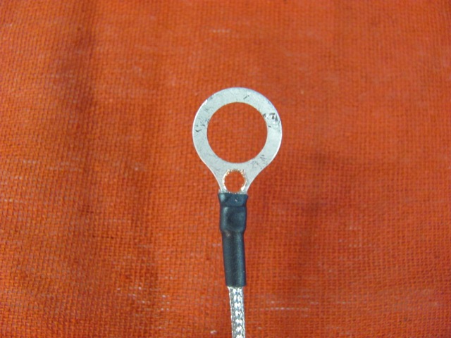
| Mar 26, 2015 - The mod calls for drilling a 11/64
hole at the base of the ring to accommodate an 8-32 screw. |
| Mar 26, 2015 - The major portion of the ring is trim off, and the remainder smoothed to form an 8-32 ring terminal. |
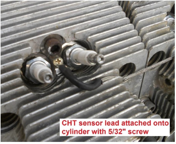
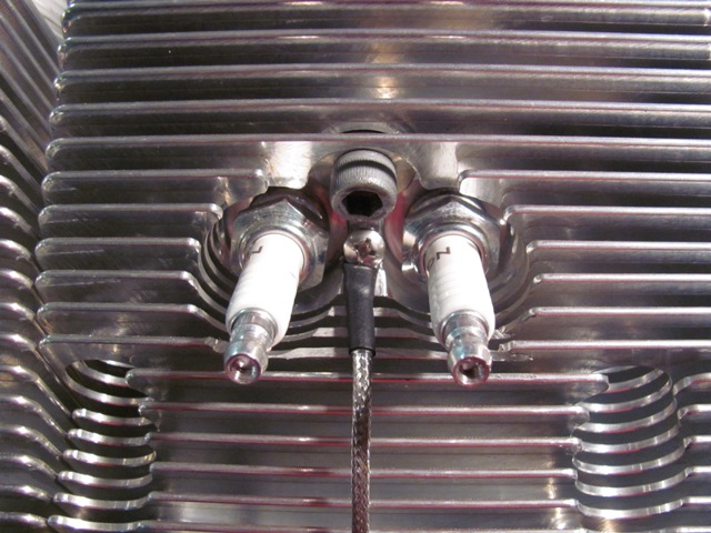
| Mar 26, 2015 - The modified sensor terminal in place. |
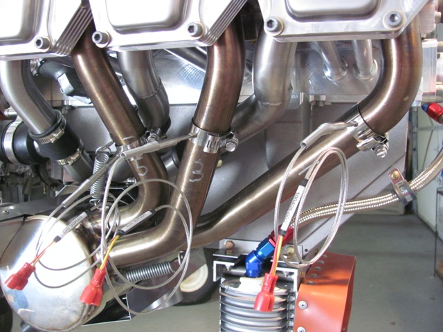
| Mar 26, 2015 - The right bank of cylinders (1-3-5) with the modified CHT sensors attached. |
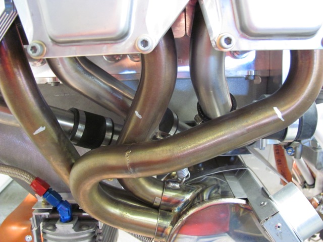
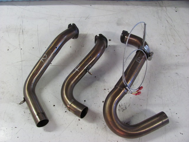
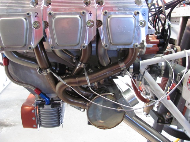
| Mar 30, 2015 - Marking location for EGT probes. Marked
exhaust pipes approximately 100 mm down from cylinder head. |
| Mar 30, 2015 - Pipes are stainless steel and very difficult to drill my hand.
Left side pipes removed and drilled using drill press. |
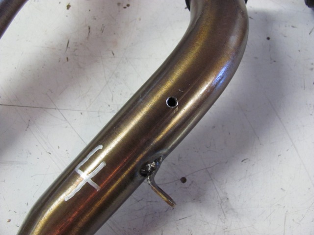
| Mar 30, 2015 - Instructions for EGT sensors call for 1/8 inch hole, but actually require 9/64 inch hole. |
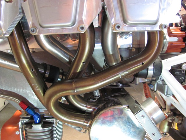
| Mar 30, 2015 - Right side pipes #3 & #5 could not be remove because there was no access to the rear cap screws. Took 30 minutes to drill by hand. |
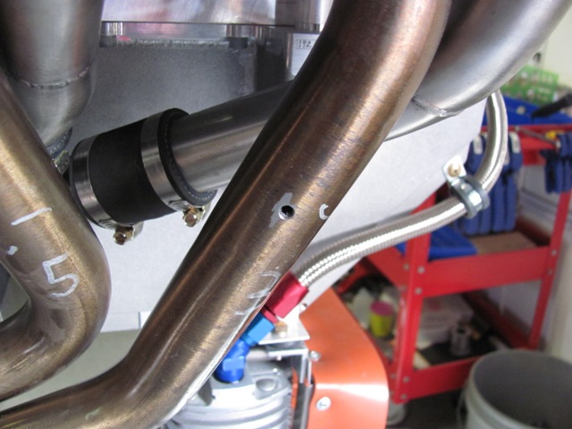
| Mar 31, 2015 - Finished drilling exhaust pipes and reinstalled. |
| Mar 31, 2015 - Installed EGT sensors on right side. |
| Mar 31, 2015 - Installed EGT sensors on left side. |
|