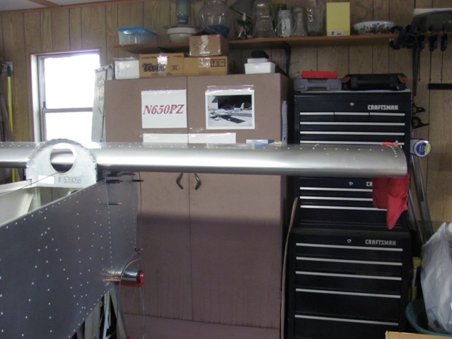
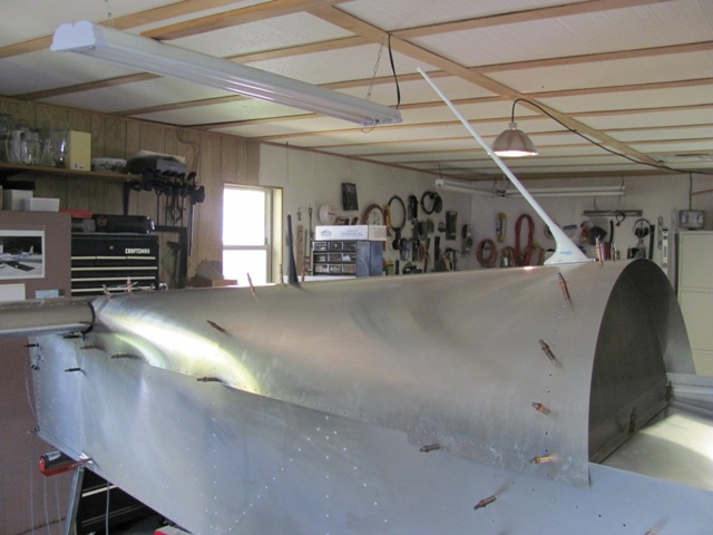
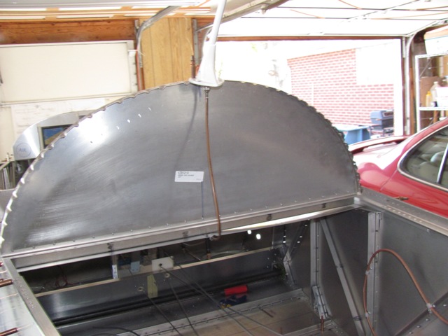
| Oct 13, 2012 - Setting the horizontal stabilizer in place.
Used levels and string line to assure accurate alignment. |
|
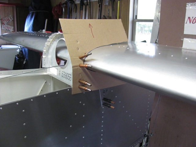
| Oct 13, 2012 - Cardboard template of stabilizer curvature. |
|
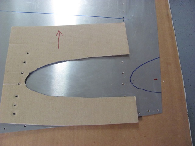
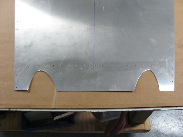
| Oct 13, 2012 - Transferring template to rear top skin.
Blue line shows area to be trimmed out to fit around stabilizer. |
|
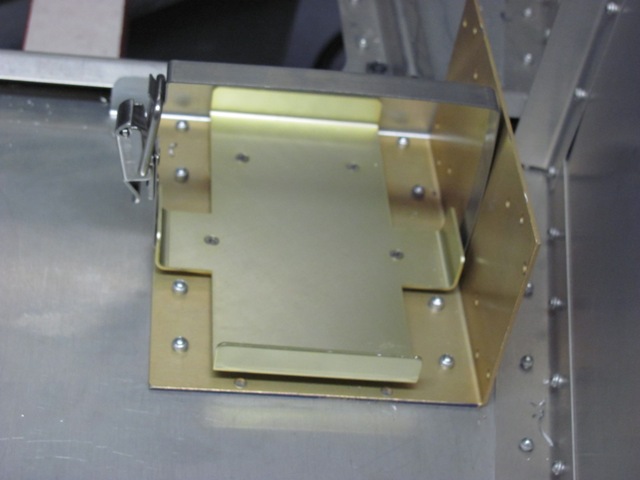
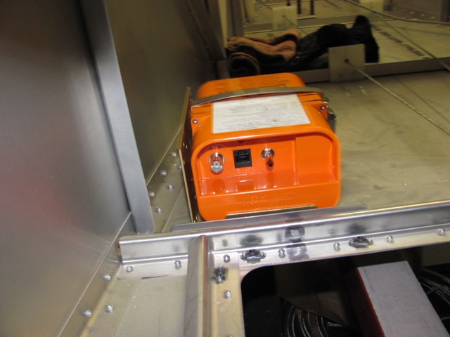
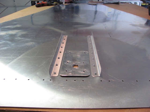
| Oct 14, 2012 - Drilled and riveted ELT mounting bracket.
Included L-angle, and blocked against hatch Z-angle frame. Added .032 in. doubler plate under bottom
skin, beneath the ELT bracket. |
|
| Oct 14, 2012 - ELT installed in bracket, showing antenna connection.
After antenna is installed, ELT will be removed and stored until ready for inspection. |
|
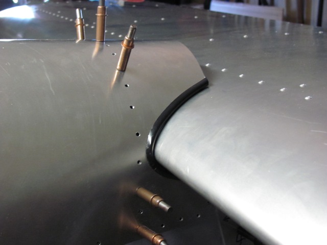
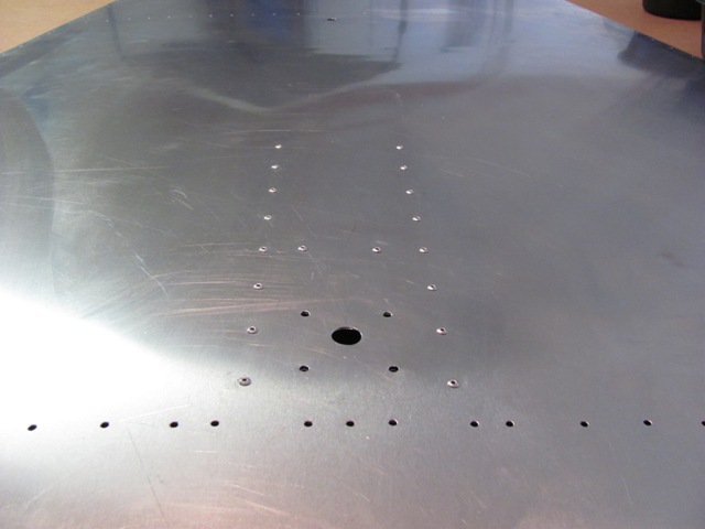
| Oct 15, 2012 - Made rough cutouts in the rear top skin to fit around
horizontal stabilizer. |
|
| Oct 15, 2012 - After several fit, trim, fit, trim operations.
Trimmed rough edges with car door edge trim. Used heat gun to enable tight corner turn. |
|
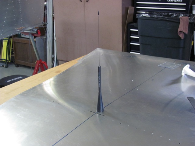
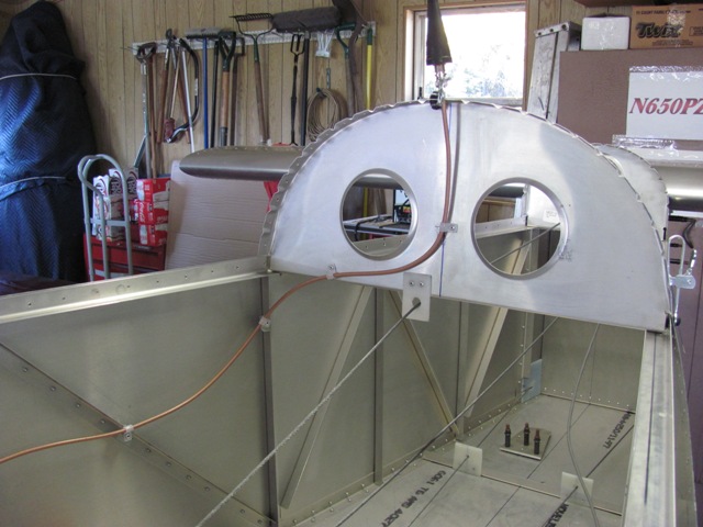
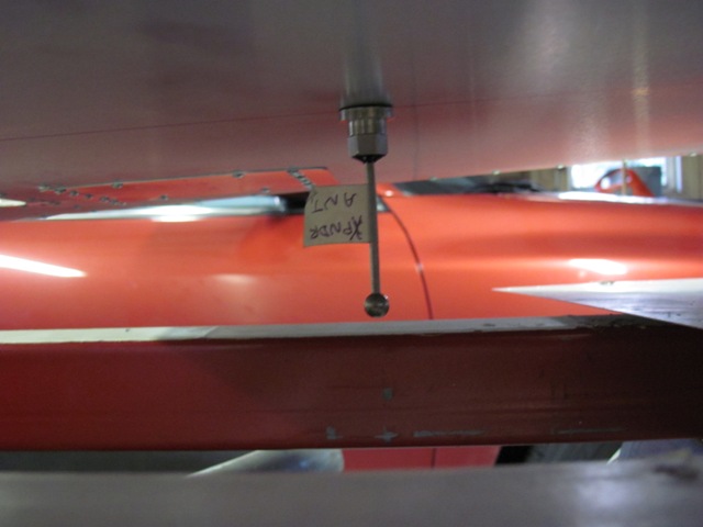
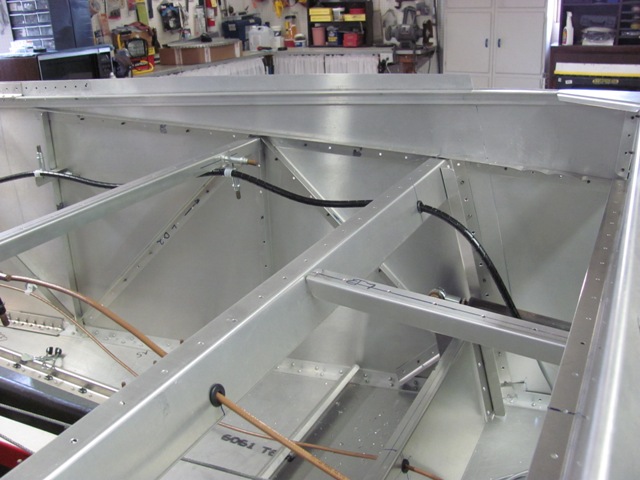
| Oct 18, 2012 - Installed ELT antenna, just in front of the middle bulkhead. |
|
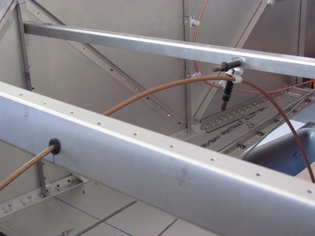
| Oct 18, 2012 - Installed COM antenna just behind the baggage compartment
bulkhead. |
|
| Oct 18, 2012 - Decided to add L-angle reinforcements for the COM antenna
to reduce/eliminate top skin flexing. |
|
| Oct 18, 2012 - Top view of COM antenna reinforcement. |
|
| Oct 20, 2012 - Trimmed step fairings to fit, then attached with clecos. |
|
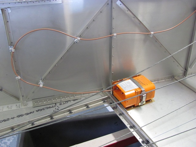
| Oct 21, 2012 - Fabricated tabs from pieces of L-angle, and used 1/4
in. plastic cable clips to make hold downs for the ELT coax. |
|
| Oct 21, 2012 - The ELT came with a 6 ft. coax cable. Rather
than try to make a new shorter cable, I just used the one supplied. |
|
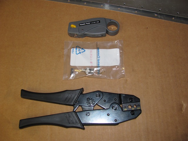
| Oct 24, 2012 - Coax stripper, BNC connector, and crimping tool. |
|
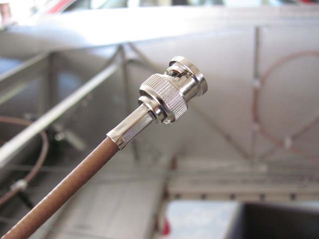
| Oct 24, 2012 - BNC connector installed on one end of RG 400 coax cable. |
|
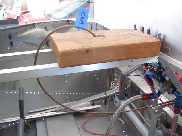
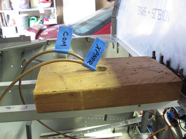
| Oct 24, 2012 - Block of wood as place holder for ICOM radio. |
|
| Oct 24, 2012 - Coax will run through center arm rest area.
Additional clips will be added once the seats and arm rest are riveted. |
|
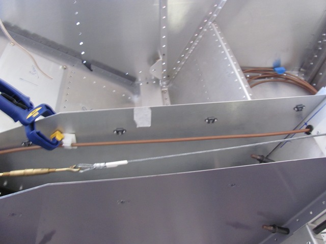
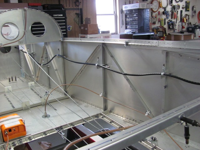
| Oct 24, 2012 - Using grommets and cable clamps to route the coax to the
back. |
|
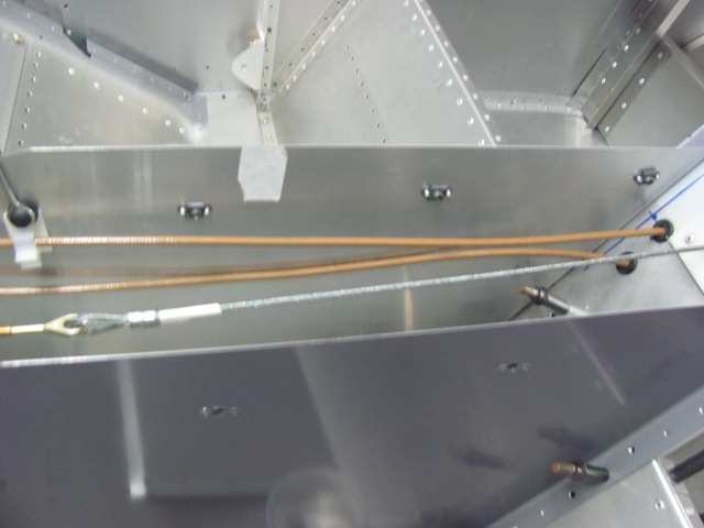
| Oct 24, 2012 - Coax passes under baggage area, then up to antenna connection. |
|
| Oct 25, 2012 - Running transponder coax. |
|
| Oct 25, 2012 - Running through center arm rest. |
|
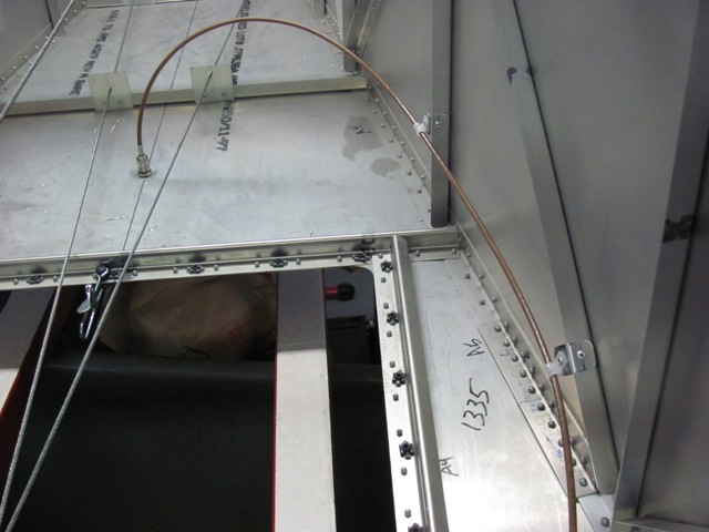
| Oct 25, 2012 - Clips to route coax away from rudder cables. |
|
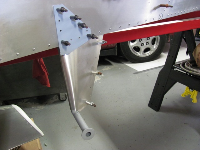
| Oct 25, 2012 - Transponder antenna installed in bottom skin. |
|
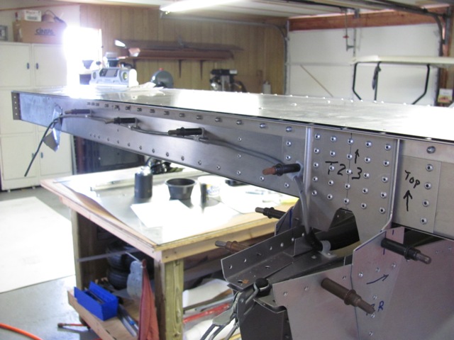
| Oct 28, 2012 - Routing elevator trim electrical cable from behind pilot
seat toward the rear. |
|
| Oct 28, 2012 - Made standoffs and used spiral wrap to protect the wiring. |
|
| Oct 28,
2012 - Routing trim electric along back edge of horizontal stabilizer to point where elevator trim servo will be located. |
|
|