|
Enter subhead content here
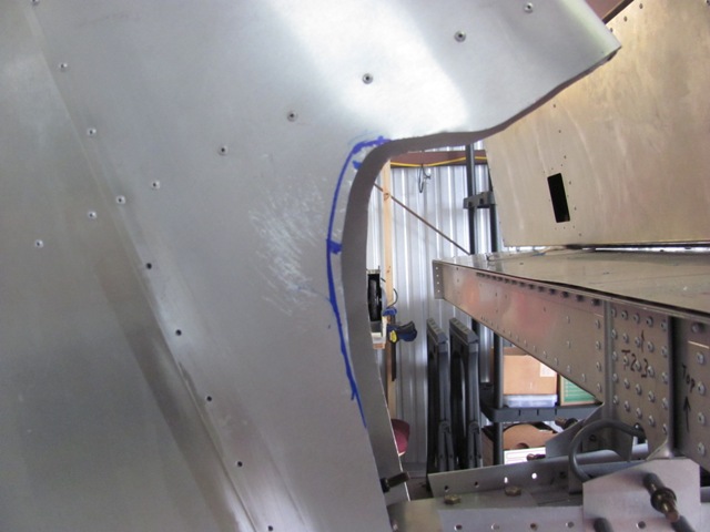
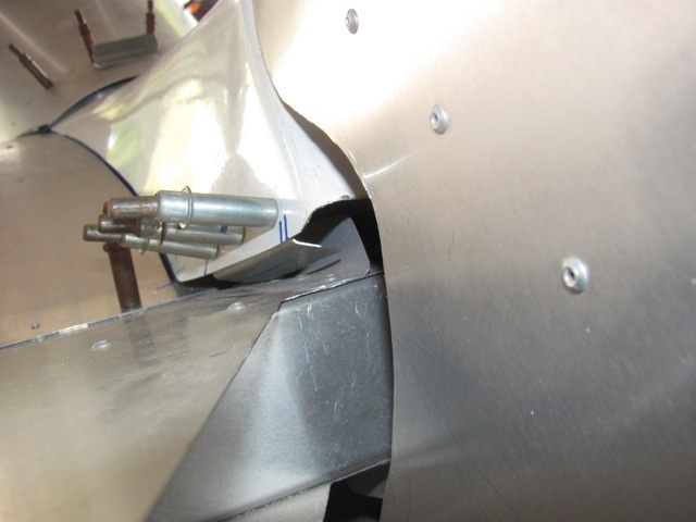
Sep 7, 2019 - After getting full rudder deflection, needed to
doing
some extra clearance trimming.
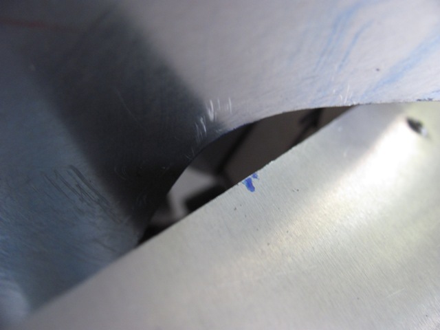
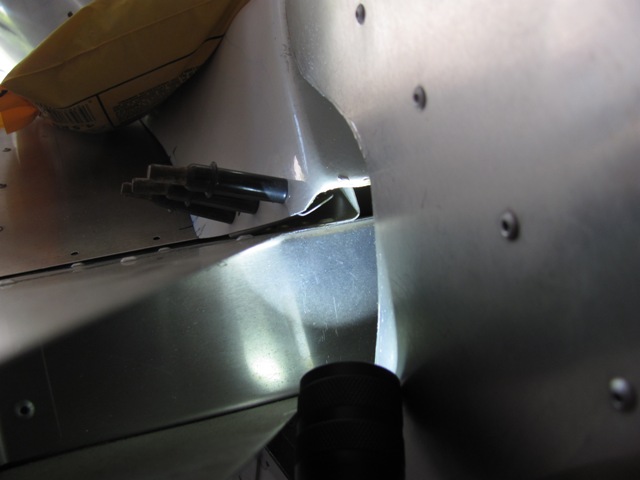
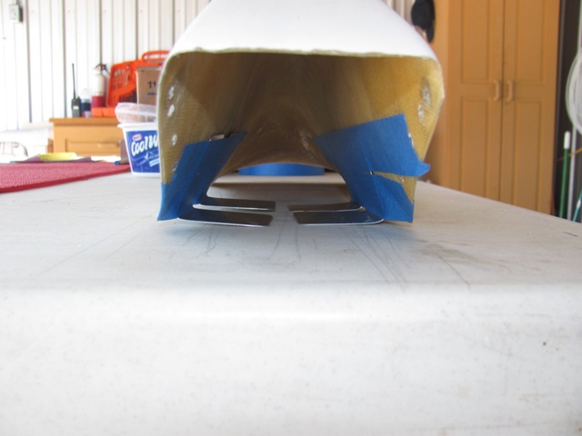
Sep 7, 2019 - Plenty of clearance now.
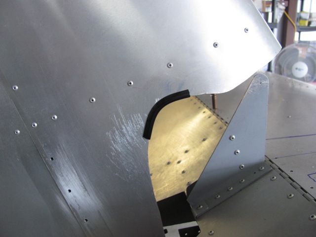
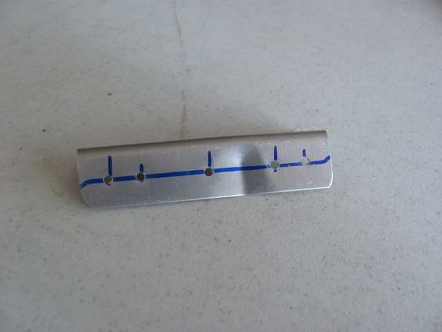
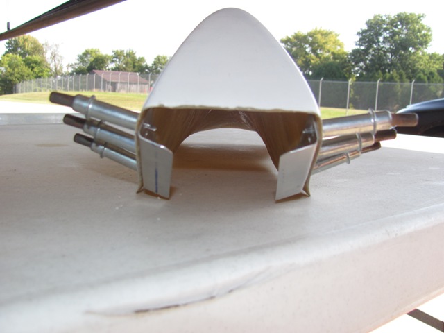
Sep 7, 2019 - Sample of edge trim material.
Sep 9, 2019 - Drilled out rivets where rudder stops attach.
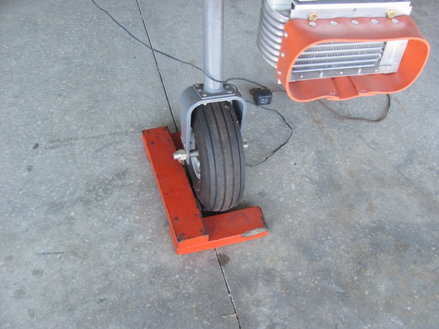
Sep 10, 2019 - Straighten nose wheel and verified rudder pedals
even
in anticipation of attaching rudder cables.
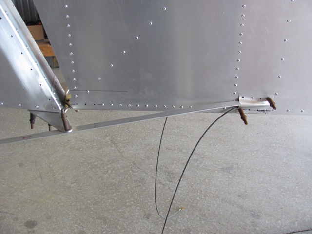
Sep 10, 2019 - Made a spacer bar of 369 mm to guarantee
rudder
straight. (Your mileage may vary. . . )
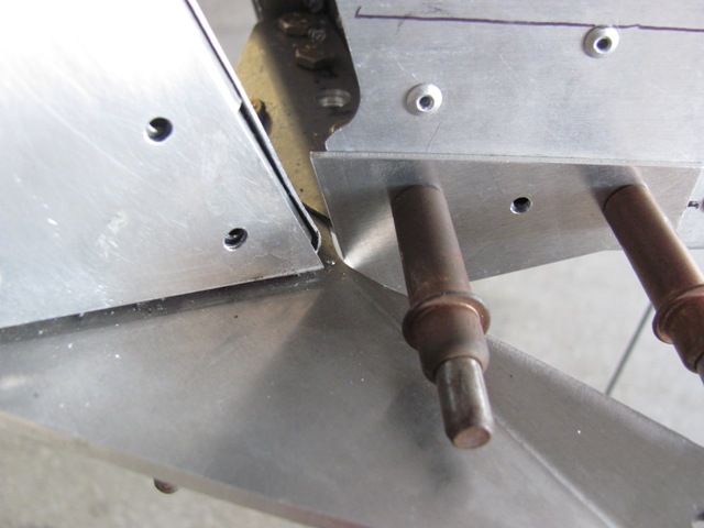
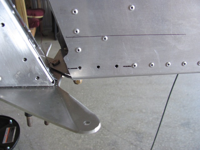
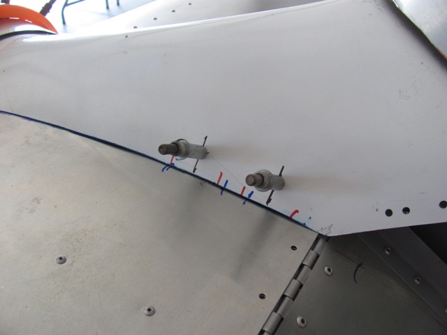
Sep 10, 2019 - Stop making positive contact with rudder horn.
This will eventually be attached with A5 rivets.
Sep 12, 2019 - Checking the points where the saddle contacts
the
elevator. Filing where necessary to get as flat as possible.
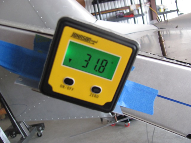
Sep 12, 2019 - The saddle acts as the upper elevator stop.
Max
upper deflection is 30-32 degrees.
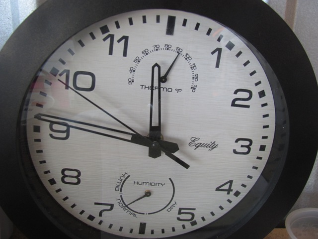
Sep 12, 2019 - September 12, 11:45 am, and it's 92 degrees
in the hanger.
Sep 13, 2019 - A short piece of L-angle is used. I put a small
crimp in to create a bend to fit the curve of the saddle.
The L-angle now inserted into its proper location inside the saddle
to act as reinforcement.
Sep 13, 2019 - The L-angle will have to be bend upward to not
conflict
with the elevator horn.
Sep 16, 2019 - Both reinforcing L-angles not attached to the
business
end of the saddle.
Sep 16, 2019 - The L-angle bent up to avoid contact with the cable horn.
Max bend for now and still have room for rivets. Can bent further afterward.
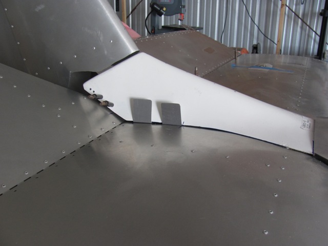
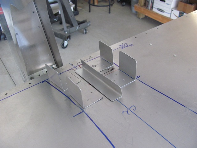
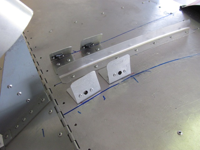
Sep 16, 2019 - Potential position for hold-down tabs.
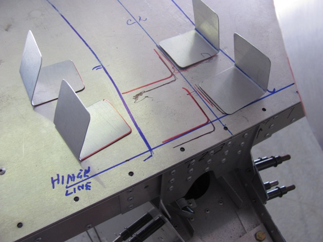
Sep 18, 2019 - Taped the hold-down tabs in the approximate locations.
Bent the tabs slightly so they will sit flat on the horizontal stabilizer.
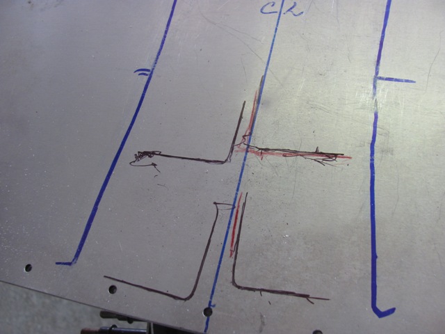
Sep 18, 2019 - These are the initial location marks as the tabs sat.
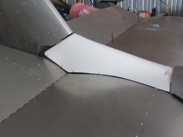
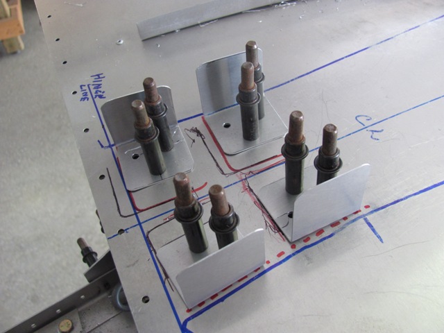
Sep 18, 2019 - After marking the elevator hinge line, tabs
adjusted
and re-marked as shown by red lines.
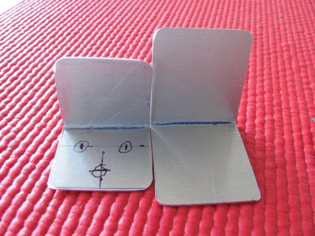
Sep 18, 2019 - Final tabs will be trimmed smaller. Circles indicate
intended rivet locations.
Sep 20, 2019 - The reduced size tabs give room for a reinforcing
L-angle
along the centerline (small sample shown).
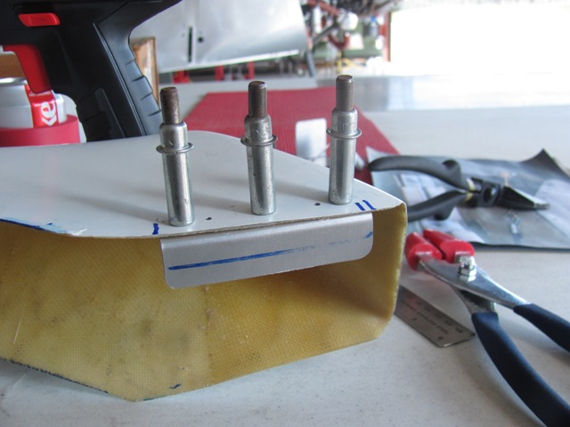
Sep 21, 2019 - The saddle hold-down tabs drilled in place.
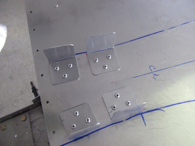
Sep 21, 2019 - Saddle hold-down tabs riveted in place, and
all
the messy lines cleaned up.
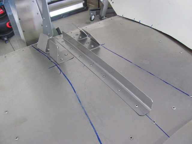
Sep 21, 2019 - Added L-angle along centerline to increase
support
in this area.
Sep 24, 2019 - The saddle drilled through into the tabs, creating
the center points for the nutplates.
Sep 24, 2019 - Nutplates riveted in place. I learned when dealing
with nutplates to enlarge the entrance hole beyond the screw size.
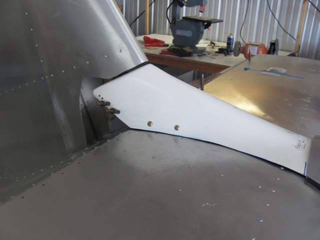
Sep 24, 2019 - The saddle attached with 10-32 screws.
Enter content here
Enter content here
Enter content here
Enter content here
|
Enter supporting content here |